Loading...
You may connect incremental Encoders to input E1 or E2, using 5-pin M12-Connectors.
![]()
Pin assignment female connector:
Pin 1 = positive power supply, +12V or +24 V
Pin 2 = Pulse signal B
Pin 3 = negative power supply, Ground
Pin 4 = Pulse signal A
Pin 5 = Pulse signal N, Reset
Guideline for choosing the right Encoder:
In order to specify the right encoder for your application, a couple of parameters need to be determined first.
- What kind of encoder should it be? Hollow Shaft Encoder or Shaft Encoder
- The diameter of the axis where the encoder should be mounted to
- Minimal and maximal speed of the axis. Measured in rotations per second
In general you might say: the more steps the encoder has, the better is the result, BUT it is important to know that the our Sensor Link is limited to a maximum of 7000 steps per second.
If the encoder turns faster and generates more steps per second, the Sensor Link will lose track of the absolute step count of the encoder. This can lead to drifting and wrong values, if the Sensor Link is being used for accurate Screen Tracking.
To avoid this, it is recommended to specify an encoder that will run at a maximum amount of 6000 steps per second.
!!! Please be aware that 6000 steps are not equal to rotation per second or Pulses per Revolution!!!
Due to the output circuit data of the encoder (which is a HTL) there are four shoulders for one circuit. That means for example: An encoder with 1500 PPR (Pulses per Revolution) generates 6000 steps per second at one full rotation per second. (4x1500 PPR = 6.000 steps/sec.)
To choose the right encoder for your application you will also need to take into consideration the following:
Is there any further gear mounted on the device which is turning?
Is the shaft, where the rotation is coming from, bigger than the axis of the encoder?
This is why you need to know the environment of where the encoder is going to be used as well as how many rotations per second the axis of the encoder will be turning.
Sensor Link has been tested with Wachendorff Encoders (www.wachendorff.com).
You may get similar encoders from other manufacturers as well, but the naming of the different signals and product specifications may vary.
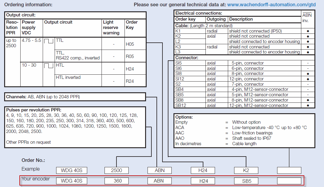
Here is an example of how to determine the right product code for a Wachendorff encoder suitable for Sensor Link.
Please Note: All the encoders are custom-built. These are not stock items!
Example encoder: WDG40S 360 ABN H24 SB5
WDG40S - is the type of the encoder – here it means that it's a shaft encoder.
360 - is equal to 360 PPR (Pulses per Revolution)
ABN - is the channel type
H24 - determines an HTL Output circuit
SB5 - determines the connector type, for Sensor Link a 5-Pin, M12-sensor Connector
Although encoders can be ordered with a fixed mounted cable, this is not recommended for service flexibility.
The connection cable between encoder and Sensor Link is available in various lengths.
Below graphic shows an example from Wachendorff:
