Loading...
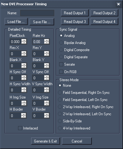
This chapter explains the dialog "Create New timing" that can be called from within the configuration menus from the DVI Processor. Please note that the term "EDID" means EDID as well as DisplayID.
The dialog offers settings to define a custom timing, which includes the settings to...:
- create an entirely new EDID
- read out a display's EDID or load it from a file
- modify EDIDs
- save new EDIDs to a file and generate a preset for the DVI Processor's output configuration menus.

Name
You can name your timing optionally. In case the timing is displayed as an preset in the output configuration menus, the name appears at the end of the entry, e.g. 1920x1080@50p custom "name". In addition, the name is also mentioned in the NVIDIA control panel as it is part of the EDID Descriptor Block.
Load File
Use "Load File ..." to load a stored EDID into the dialog. You can edit the timing, generate an output preset or save it as an *.edid file.
Save File
Use "Save File ..." to export the currently displayed EDID timing into a *.edid file.
Read Output 1...4
These buttons generate a timing based on the information from the device plugged into the according DVI output. Note that SDI outputs can not be read-out. The timing is displayed in the dialog. Note that all values will equal zero if no valid EDID can be read. You can edit the timing, generate an output preset or save it as an *.edid file.
Generate & Exit
This option generates an output preset based on the currently displayed timing and closes the dialog.
Please note, that it is of importance from which menu you opened the dialog. If you were in the DVI "Dual Mode" (2in 2out), your EDID is assigned to the graphics card outputs one-to-one. In case you were in a DVI "Quad Modes" (2in 4out, either Single Link with max. 720p or Dual Link with max.2k), your EDID is automatically doubled as the graphics card outputs are split in the Quad Modes. In both cases the displayed timing in this dialog and the entry in the menus always refer to the Processor's outputs.
The new EDID is saved as an *.edid file in the according sub folder under C:\system\LCD_Menu\Quad DVI SDI Modes. It also appears in the according menu with a distinct name e.g. 1920x1080@50p custom (optional name). Go to the DVI Processor's output configuration menu and select it to apply it to DVI output 1-4 whilst the incoming signal is set automatically.
Cancel
Use "Cancel" to close the dialog and discard all settings.
EDID Description
The EDID Description shows the content of the "First Detailed Timing Descriptor Block" along with the "Monitor Name" out of the EDIDs "Descriptor Block 2".
The displayed information changes automatically when "Load File" or "Read Output 1...4" is used. You can edit the timing, generate an output preset or save it as an *.edid file as described above.
Detailed Timing
Name |
Read out or change the monitor name with a maximum of 13 characters. |
PixelClock |
This value shows the signal's PixelClock in MHz. |
Rate Hz |
This value shows the signal's Refresh Rate in Hz when an EDID is loaded. It results of all other definable settings regarding pixel count and PixelClock. |
Res X |
This value shows the signal's active pixel per horizontal line. Active pixels are the shown ones within a display device and equal the horizontal resolution. |
Res Y |
This value shows the signal's active lines per image. Active lines are the shown ones within a display device and equal the vertical resolution. |
Blank X |
This value shows the signal's total horizontal blanking pixels including (definable) front porch, (definable) sync width and (resulting) back porch. |
Blank Y |
This value shows the signal's total vertical blanking lines including (definable) front porch, (definable) sync width and (resulting) back porch. |
H Sync Off |
This value shows the signal's horizontal sync offset (front porch) in pixels. |
V Sync Off |
This value shows the signal's vertical sync offset (front porch) in lines. |
H Sync Width |
This value shows the signal's horizontal sync width in pixels. |
V Sync Width |
This value shows the signal's vertical sync width in lines. |
H Img Size |
This value shows the monitor's horizontal image size in mm. This information value is optional and has no influence on the signal processing. |
V Img Size |
This value shows the monitor's vertical image size in mm. This information value is optional and has no influence on the signal processing. |
H Border |
This value shows the signal's horizontal border in pixels. |
V Border |
This value shows the signal's vertical border in lines. |
Interlaced |
This check box shows if the signal is interlaced (checked) or progressive (unchecked). |
Sync Signal
Readout or select the desired sync option required by the signal.
Depending on the chosen sync option, there are additional check boxes to be de-/activated.
Stereo Mode
Readout or select the desired Stereo Mode required by the signal.