Loading...
This chapter explains the general and location settings in the AirScan unit that is part of the AirScanManager device. For more information please see the introductory chapter.
There are currently three types of AirScan units that can be added to an AirScanManager (plus one virtual unit). These units hold a connection to and settings of a physical device which will each deliver input data to the AirScanManager they are bound to.
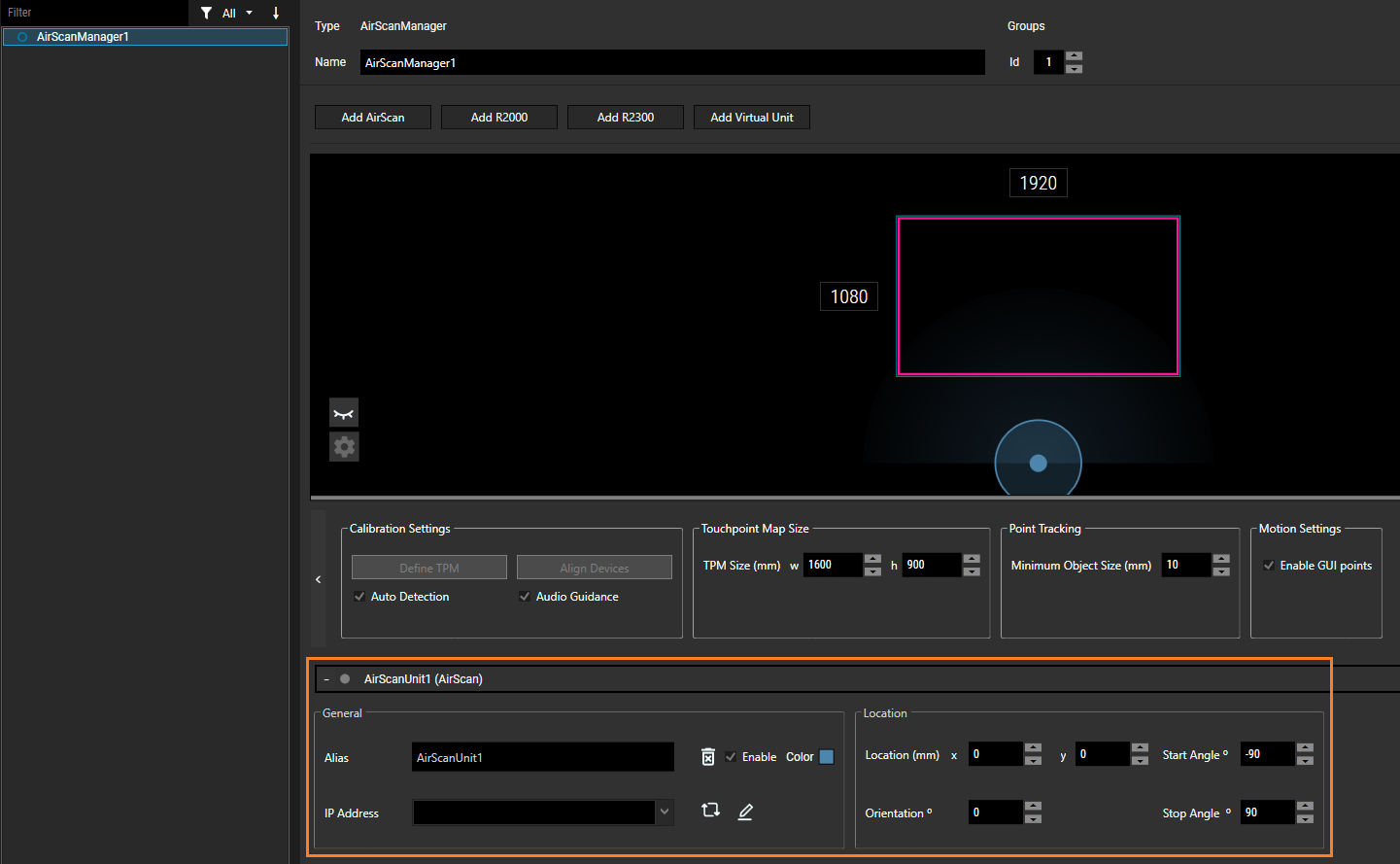
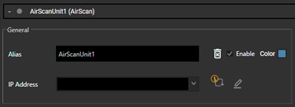
Alias:
Enter the name of the device.
IP Address:
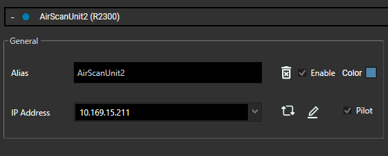
Enter the IP address by either selecting the Auto Discovery icon next to the IP Address field or manually. The unit displays a solid blue dot to indicate it is online and is visible on the canvas. This is not available for the Virtual Unit selection.
Auto Discovery:
Auto discovery might initially be unavailable for Christie AirScan devices which is indicated by an orange information icon. ![]()
For information on how to solve the issue, hover over the icon. Complete the following steps:
2.Relaunch Widget Designer.
3.Power cycle the device.
Then next time auto discovery is used, previously used IP address of the same unit type displays in another field entry below as "In Use".

Pen:
Select this icon to set a new IP address and subnet mask for the device. This is not available for the Virtual Unit selection.
Trash bin:
Remove the respective unit.
Enable:
Hide or show the respective device in the canvas. This option helps to disconnect single units on an AirScanManager. If a unit is disabled, the system works as if this unit does not exist. The AirScan Unit Representation (AUR) of the unit and its readings inside the AMP are not shown and connection status changes from a solid blue dot a solid grey dot.
Color:
Choose a color for the unit instance. This helps to distinguish between multiple connected similar units. The chosen color is displayed as the color of the unit, unit readings, Field of View (FOV), and AirScan Unit Representation (AUR).
Resolution (R2000 only):
The default value is 5040 samples per scan. The Resolution defines the number of angular increments of technically possible field of view (360°).
The values can range between 72 (~5.000°) @30Hz and 25200 (~0.014°) @10Hz.

For R2300, the unit has the same settings as the AirScan unit except for the added option of Pilot. This activates a pilot laser that helps adjust the scan plane.
Virtual Units provide virtual touch points which might come in handy, i.e. when there are no physical units present, yet. You might want to check your project setup including interaction and scripting when using touchpoints, prior to going on site and connecting to real units.
Since this unit is part of the application there is no need for an IP address to connect to. However, this unit provides the following additional settings:
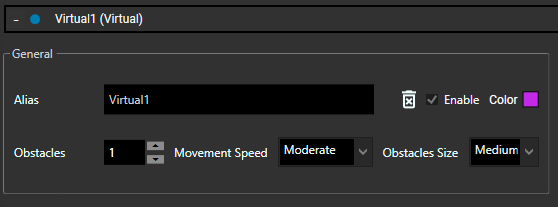
Obstacles:
The default obstacle count is 1 and can be changed to a maximum of 1000. This count determines the number of obstacles to be displayed on the canvas.
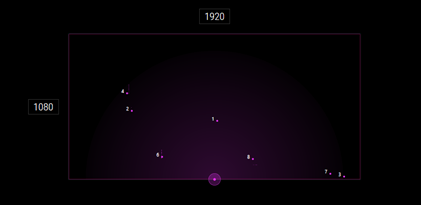
Movement Speed:
Slow, moderate, or fast movement speed can be set for the obstacle.
Obstacle Size:
The obstacle size can be set as small, medium or big. Try to see which setting works best for your specific scenario.
The Location settings are available to the right of the General settings.

Location X/Y:
Enter the location in mm of the AirScan unit. This is relevant when working with multiple units. The semi-automatic 'Align' feature should already provide correct values, users can still manually tweak those, whenever necessary.
Orientation:
Enter the orientation in degrees.
Start Angle and Stop Angle:
Enter the start and stop angles in degrees. The value ranges depend on the unit type:
•AirScan: -90 to 90
•R2000: -180 to 180
•R2300: -50 to 50