Loading...
This chapter explains the AirScanManager Preview (AMP) of AirScanManager in Widget Designer. For more information, please see the introductory chapter.
The black canvas represents the AirScanManager Preview (AMP).
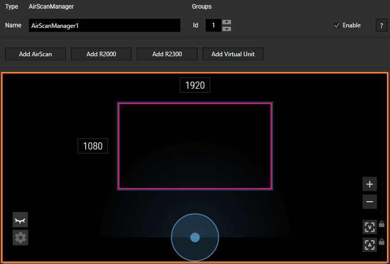
There are two modes for the AirScanManager page: Standard mode and Advanced mode. Select the Settings icon ![]() in the AMP to switch between the modes.
in the AMP to switch between the modes.
In standard mode, the following buttons are available:
 |
Settings Select this button to switch between Standard mode and Advanced mode. |
 |
Hide Touchpoints Select this button to hide touchpoints in the AMP. Once this button is selected, the button changes to a Show Touchpoints button. |
 |
Show Touchpoints Select this button to make touchpoints visible in the AMP. Once this button is selected, the button changes to a Hide Touchpoints button. |
 |
Zoom In Use the + button to zoom in on the center of the visible area. This increases the same amount as when using the mouse wheel. |
 |
Zoom Out Use the - button to zoom out of the center of the visible area. This decreases the same amount as when using the mouse wheel. |
 |
Fit to View Use the Fit to View button to zoom in or out, so that all elements are shown in the AMP. If the lock icon is pressed it gets red and this view is locked. |
|
Fit to Active Area Use the Fit to Active Area button to have the TPM fit to view. If the lock icon is pressed it gets red and this view is locked. |
In addition, the following properties are also available in standard mode:
- Mouse control
- Standard options in Touchpoint Map Size, Point Tracking, and Motion settings
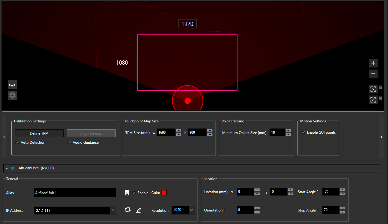
In advanced mode, the following buttons are available:
 |
Settings Select this button to switch between Standard mode and Advanced mode. |
 |
Hide Touchpoints Select this button to hide touchpoints in the AMP. Once this button is selected, the button changes to a Show Touchpoints button. |
 |
Show Touchpoints Select this button to make touchpoints visible in the AMP. Once this button is selected, the button changes to a Hide Touchpoints button. |
 |
Zoom In Use the + button to zoom in on the center of the visible area. This increases the same amount as when using the mouse wheel. |
 |
Zoom Out Use the - button to zoom out of the center of the visible area. This decreases the same amount as when using the mouse wheel. |
 |
Fit to View Use the Fit to View button to zoom in or out, so that all elements are shown in the AMP. If the lock icon is pressed it gets red and this view is locked. |
 |
Fit to Active Area Use the Fit to Active Area button to have the TPM fit to view. If the lock icon is pressed it gets red and this view is locked. |
 |
Trigger and Mask Area Select the T+ for trigger and M+ for mask. Trigger area To rename a Trigger area, hover over the name until the mouse pointer turns into a textcursor. Enter the new name and complete one of the following to confirm the change:
Mask area |
In addition, the following properties are also available in Advanced mode:
World settings
Mouse control
Additional options in Touchpoint Map Size, Point Tracking, and Motion settings
Use the scroll buttons (< and >) to scroll over the Advanced properties.
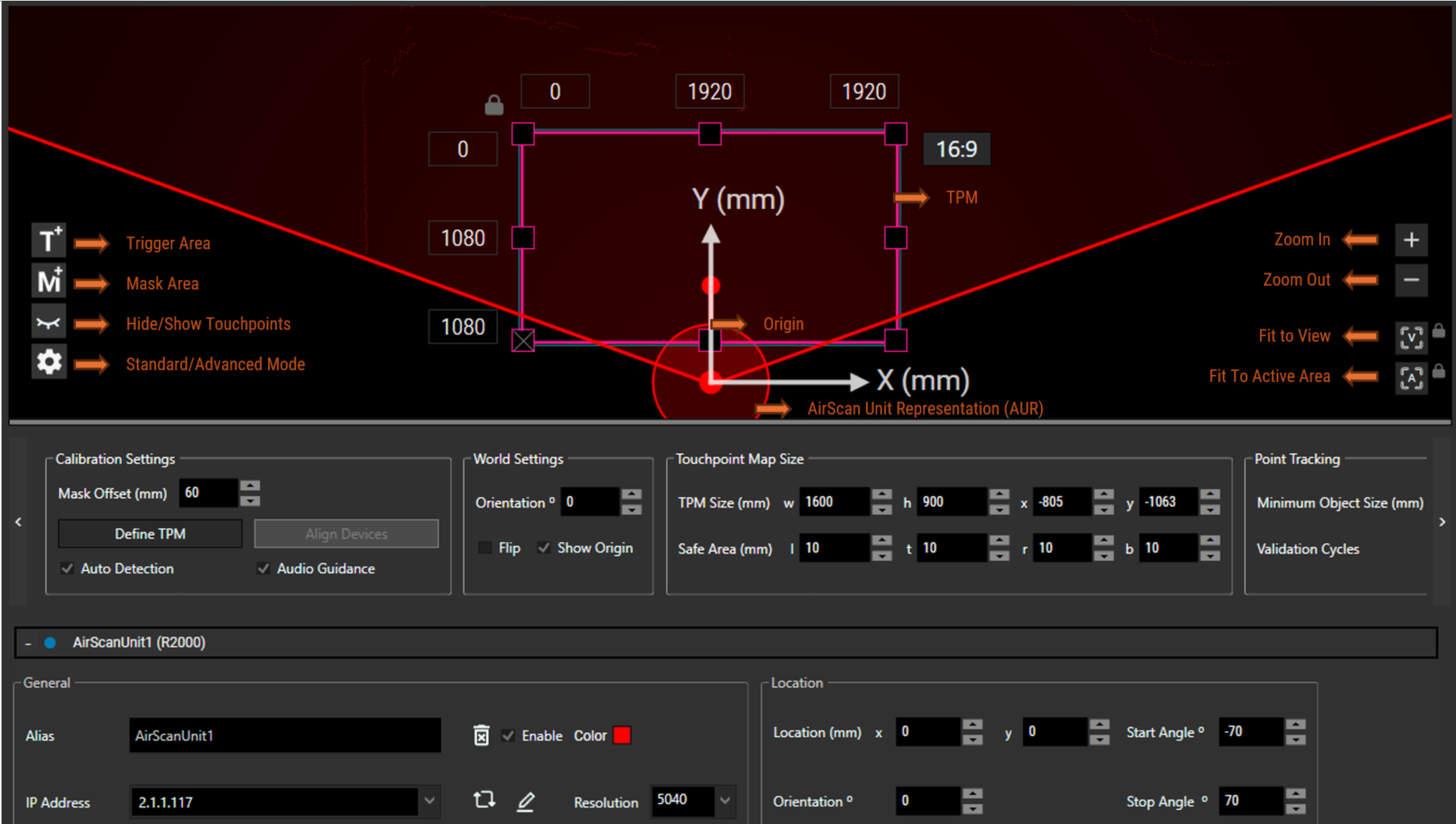
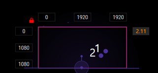
In AMP, the pink rectangle indicates the Touchpoint Map (TPM). Its default output resolution is 1920 x 1080 and is shown in the middle of the TPM boarders. The TPM size is merged to this output resolution. To change the output resolution double click onto the size values. In Advanced Mode you can put an offset onto this output resolution to shift the Touchpoint values e.g. onto the second screen. On the one hand you can enter the offset directly (zero values upper left corner in picture above) and the end pixels are calculated (value upper right for width, value bottom left for height). On the other hand you can decide to enter the end pixels (upper right for width and bottom left for height) and the offset is calculated. The TPM resolution can not be calculated. A touchpoint is generated from the connected AirScan Unit when it is inside the TPM and matches the minimum object size.
To edit the Touchpoint Map Size enter values for width and height in the Touchpoint Map Size settings. For small changes you can use the arrows in the width (w) and height (h) fields. In Advanced mode you can resize the TPM by Drag and Drop the small rectangles at the corners or boarders of the TPM inside the AMP.
To lock the TPM size and position, use the lock button in the upper left corner of the TPM. Once locked, the icon gets red and the TPM cannot be moved, resized, or deleted.
The aspect ratio is set to 16:9 by default and it is shown in the upper right corner of the TPM. Changing the values in the input controls for output resolution does not change the TPM size. If the aspect ratio of TPM size matches the aspect ratio of the output resolution the aspect ratio is written in white letters. If it is not matching the shown aspect ratio shows the TPM aspect ratio and is written in orange letters.
In Standard Mode, the TPM can be used to generate a fake touchpoint using the mouse. To do this, place the cursor inside the TPM boundary and keep left clicking the mouse.
The AirScan Unit Representation represents an actual device which is part of the setup. Location, Orientation, and Field of View can be set on each unit independently.
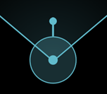
The AUR unit is represented by a circle with a dot and a rotation pivot in the center. There is also a handle to change the orientation of the device. Start and stop angles of the respective unit (also shown in Location properties of the unit) are represented by two bars outgoing from the AUR centre. For more details see below. The active scan area is indicated by a color gradient in the color of the unit between the start and stop angles.
Start and Stop Angle:
In the AMP, you can change the start and stop angle of the device by dragging its handle. Hover over an edge line from the start or stop angle until the mouse cursor changes to a hand icon. The drag and drop line shifts in 1° steps. The current value is displayed near to the mouse cursor and it gets updated in the Location settings of the unit as well.
Adjust the start and stop angle within the particular range of each device type:
•AirScan (Legacy): -90 to 90
•R2000: -180 to 180
•R2300: -50 to 50
Do not change the start and stop values during "Define TPM" and "Align Units". For calibration, the default values to cover everything are used. After, custom values can be set to adjust to the setting.
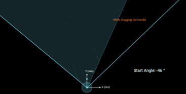
[Start angle]
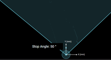
[Stop angle]
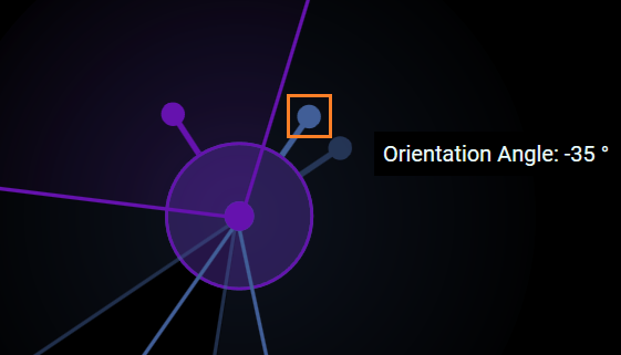
Orientation Angle:
Similar to the stop and start angle feature, the orientation angle of the device can be changed by dragging the AUR rotation pivot. The mouse moves along with the handle. The current value for orientation is displayed near the mouse pointer and is also automatically updated in the Location settings.
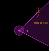
Field of View (FOV):
FOV defines the touchpoint scan or detection area with respect to an AirScan Unit. The FOV lies as a region between the start and stop angle of the device and is marked with a color gradient in relation to the color of the Unit. The representation of the FOV updates depending on changes to the start or stop on the AUR or the unit properties.
