Loading...
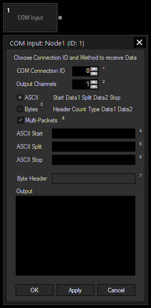
The Com port input node allows receiving either ASCII or Byte values over a local COM Port connection. The COM Port connection needs to be enabled in the Connection Manager.
This input node can output by default any incoming packet as text if no ASCII filter is applied.
This node can be found under Nodes > Input > Connections > Com Input

COM Connection ID:
Enter the ID of the COM Port connection.
Output Channels:
Set the Amount of Output Channels of this Input Node.
Input Value 1 will output Data 1, Input Value 2 will output Data 2, etc.
ASCII Mode:
The ASCII Mode allows creating a custom ASCII protocol for data transfer.
Multiple data can be separated by the split string.
To determine the Start and End of the message, use the Start and Stop strings.
ASCII Start, Split and Stop:
Enter values as string, dec or hex value. Please refer to Syntax TCP- / UDP- / Serial messages.
Bytes Mode:
The Byte protocol allows data transmission based on a byte stream.
First send the header with any amount of Bytes.
Followed by the data count as 4 Byte Integer. Each piece of data, i.e each 4 Byte Integer or each 8 Byte double, counts as one. Please take into account that the processing uses a little-endian Byte order, meaning that the lowest byte comes first.
Followed by a single Byte to describe the data type used (1 = 4byte integer, 2 = 8byte double).
Followed by one or multiple data sets of the specified type, also in little-endian Byte order.
Example: This byte stream transmits one integer with value 5000, the header is "WD!":
[87 68 33 1 0 0 0 1 136 19 0 0]
- Header: 87 68 33
- data count: 1 0 0 0
- data type: 1
- data: 136 19 0 0
Byte Header:
Enter values as string, dec or hex value. Please refer to Syntax TCP- / UDP- / Serial messages.
Multi-Packets:
If the COM packets are being received in parts, this option allows reading all part packets as one.
With Widget Designer version 6, all nodes support so called node commands. Node commands access functions (i.e methods) from a node and / or set a parameter (i.e. property).
Enter "node", followed by the according ID and a dot and a list will pop up showing all available commands for the node. For instance, Node1.TintColor.SetRGB(125,0,255), colors the node in purple.
In addition, the node properties with a parameter ID (the small superscript number) can be edited via the command Node1.SetParam(ID,new Value) or WDNodeSetParam(NodeID,ParamID,Value).
The Node generates the following output:
- Input Value 1 up to Input Value X (X = number of entered output channels).