Loading...
This topic describes the requirements for the IR ID tracking method regarding hardware and environment. For general information about IR ID tracking and links to other chapters please see the topic ID Tag Tracker.
Hardware-wise the IR ID tracking method requires tags, cameras, (a switch), and a computer running Widget Designer. The surrounding environment must be suitable.
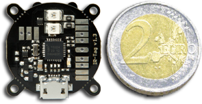
The tags can be purchased through your local Christie distributor. You can choose between an "ID Tag" that provides one configurable ID and the "Quad ID Tag" that provides up to four configurable IDs.
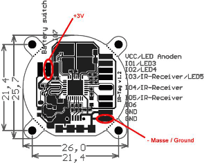
(Single) ID Tag  The onboard or added LEDs blink in a certain pattern according to the set identification number. The LEDs' luminosity can be adjusted whilst only the onboard ones can be powered by 100%. Additional LEDs can be driven with max. 70%, independent from the power source. You may set up to use one or both onboard LEDs and up to three possible additional ones. A brighter tag allows a more distant camera, a more lightened surrounding and a more robust tracking. On the other hand it consumes more power.  - onboard hearing cell holder: holds two button cells; smallest space; feeds one LED with 70%; battery life span approx. 10 hours (as soon as the batteries are activated this span cannot be stopped!) - onboard Micro-USB interface: allows to plug the delivered battery (with four 1.5 AA batteries); a battery pack lasts up to 24 hours; auxiliary battery packs should deliver 4.2 to 6.5V - custom power source: the pads allow to add another power source with max. 3V The tag can be configured via the onboard Micro-USB interface. Connect the tag via the delivered USB cable (Micro-USB to Standard Type A plug) to your computer running Widget Designer. The configuration involves the number and power of the IR LEDs as well as the brightness of the blue control LED. Further, the blinking mode including the ID can be set up. See below for more details regarding the software settings. The settings are stored in the tag, allowing to unplug it from the computer to change back to the delivered battery pack. |
Quad ID Tag  The connected LEDs blink in a certain pattern according to the set identification number. Each port can be numbered individually. The LEDs' luminosity can also be adjusted. A brighter tag allows a more distant camera, a more lightened surrounding and a more robust tracking. On the other hand it consumes more power. The tag can be configured via the onboard Mini-USB interface. Connect the tag via the delivered USB cable (Mini-USB to Standard Type A plug) to your computer running Widget Designer. The configuration involves the options for the brightness of the IR LEDs as well as the brightness of the blue control LED. Further, the blinking mode including the four IDs can be set up. See below for more details regarding the software settings. The settings are stored in the tag. |
The cameras supported are third-party motion capture cameras from the OptiTrack system developed by the company NaturalPoint. Please contact an OptiTrack distributor if you are interested as they cannot be purchased through your Christie distributor.
The implemented and supported OptiTrack models are called:
V100R2
Flex13
Prime13
Prime17
Prime17W
Prime41
s250
The camera models differ in resolution, frame rate, field of view (opening angle), max. tracking distance, latency, etc. Please refer to the "Compare Cameras" website offered by NaturalPoint.
The question how many cameras are needed and where they need to be positioned depends first of all on the choice to track 2D or 3D. As mentioned above, to capture the 3D position of a tag, a minimum of three cameras must "see" it at any time. For the 2D position, only one camera is needed. Secondly, the maximum distance from a camera to a tag must be defined by combining the camera model's specifications in theory with the stage environment in field. This is influenced by light, the stage setup itself, object movement etc. Please see the below paragraph about "Environment". Afterwards, you may position the cameras in such a way that they cover the area of interest so that one tag is seen by either one or three cameras at any time.
Please keep in mind that the cameras' position should be as static as possible. If they are mounted with other devices such as moving lights on a truss, we strongly advice to check whether any light cue state moves the cameras so much that it worsens the tracking too much.
An PoE Ethernet switch is needed when working with cameras with an Ethernet interface, e.g. the s250e or the Prime models. We recommends to consider the product recommendation from NaturalPoint. They offer accessories including switches. As well they provide detailed information about the specification a switch must meet as not all PoE switches are suitable for use with OptiTrack PoE Ethernet cameras. Quoting their FAQ page: " Ethernet cameras require PoE or PoE+ Gigabit (1000 Mbit/s) Ethernet switches. Standard PoE switches must provide a full 15.4 watts to every port simultaneously and PoE+ switches must provide a full 25 watts to every port simultaneously." Please consider that the required power is provided on all ports simultaneously and not only to a subset of ports whilst downgrading other ones. The cameras will not function properly when insufficient power is available to them.
Same applies to the bandwidth per port. "(...) the switch must support Gigabit (1000 Mbit/s) for every port. Connecting multiple PoE switches in a star topology to a non-PoE Gigabit uplink switch is recommended for larger camera counts." It is not recommended to connect more than 4-8 cameras on one switch.
As the Ethernet cameras assign themselves an IP address, the switch must not provide a DHCP Server!
The cabling between Ethernet cameras and the switch must be done with Cat6 or Cat7 cables; Cat5/Cat5e/etc not supported. For the USB cameras (e.g. V100:R2) the USB cable length must match the NaturalPoint recommendations. Both camera types, Ethernet and USB, draw their power from the connected "data" cables, an additional power supply and connection is not needed.
Lastly, the Widget Designer communicates with the cameras, processes all the (image) data and extracts the object's position in real-time. Further this data is processed according to your needs and output via Art-Net to a lighting desk or via network to Pandoras Box for example. Hardware-wise it is recommended to meet at least the specifications from a Pandoras Box Workstation. Please contact your local distributor for more detailed information. Next to the network hardware (cables, switches, etc.), the type of Widget Designer hardware (network card, processor...) determine the amount of cameras and tags per system. As a very rough rule of thumb, one Widget Designer hardware and one LAN (local area network) may process the data of six cameras and 32 tags. Several options may increase or decrease this number.
The more tracking data is processed (e.g. from the cameras to WD) the more it is recommended to separate data flows from each other. This can be either done by using manageable switches or with network cards that offer multiple network adapters / NICs (Network Interface Card, physical RJ-45 connector). In the depicted example, the camera tracking data, interactivity data and show data from Pandoras Box are separated.
Widget Designer and Widget Designer Unlimited edition support the tracking node itself and the tag configuration. Widget Designer Free Version supports only the tag configuration.
The setup for Widget Designer is described in the "Installation" chapter. If you would like to configure tags, connect one via the delivered USB cable (Micro-USB to Standard Type A plug) to your computer. Use the USB-driver "coousb-driver v6.0.13.0" (or a newer one) to finish the hardware installation of the device. Further steps are described in the chapter "Config ID Tag".
If working with Ethernet cameras, the computer must be set up with a static IP address in a range and subnet mask freely chosen.
If working with USB cameras, please make sure to install the driver NaturalPoint provides.
The user interface offers several settings including the configuration of the tags, the cameras, the tracking itself including the management of objects' properties and finally the system to which all this data is send. The following pages will explain all option in the user interface.
The surrounding environment must match the needs of an optical tracking method based on infrared light. In the nature of things, any other infrared light source influences the stability of the tracking system. Please note, that many materials (glass, metal, etc.) reflect infrared light.
To reduce light noise, it is possible to adjust the cameras' sensitivity and tags' luminosity. These settings help to get rid of most unwanted light sources but still see the tag's light. In addition, masking is available. A mask can be used to exclude certain areas from the image a camera sends to Widget Designer, for instance areas outside the stage or too bright areas on stage. However, these areas need to be static and will also absorb the tag's information.
It is highly recommended to schedule sufficient time on site to cope with these interferences. Keep in mind that any changes done to the stage setup and scenery could influence the tracking behavior.