Loading...
This chapter explains how to set up a patch within a Modbus Client device. To learn how to set up a Client, please refer to the previous chapter Modbus Client Configuration. If you would like to learn how to use values with Modbus, please refer to the next topic Using Modbus.
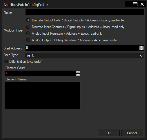
To open the Modbus Patch Configuration dialog, click "Add" or "Edit" at the bottom from the Modbus Client Configuration dialog.
Modbus specifies four different input/output device types:
- Discrete Output Coils (digital output, 1bit)
- Discrete Input Contacts (digital input, 1bit)
- Analog Output Holding Registers (analog output, 16bit)
- Analog Input Register (analog input, 16bit)
Note that both output options are "read-write" allowing to get and set data whilst the input options are "read-only" allowing only to get values.
Widget Designer also supports the possibility to swap the byte order of sent and received data packets, as well as a 32bit data size.

Enter a name for your Modbus patch. It may consist of letters (lowercase or capital) and numbers, as well as underscore "_", the first character must be a letter. A valid name would be e.g. "Motor_123". The name has to be unique in WD.
Scripting members for this Patch will be available when typing this name in a scripting field after the Clients name followed by a dot. This is explained in the chapter Using Modbus.
When using nodes (e.g. the Modbus Input) the name is available in the respective drop-down menu.
Select here what kind of Modbus device you want to address with this patch.
Enter here the start address of your patch. Please bear in mind that some hardware devices require specific addresses.
Select how the incoming data should be interpreted. You can select between unsigned and signed readouts - both for 16 or 32 bits of data; the Modbus native datatype is an unsigned short (= uint16).
Int16 and UInt16 are the default configuration for one data word. Int16: values -32768 to 32767, UInt16: value 0 to 65535.
Int32 and UInt32 require two data words (achievable e.g. with using two combined 16bit registers).
The discrete in- and outputs only contain a 1bit value (0 or 1), which are still transmitted as one 16bit word.
The data type FHPP, the Festo handling and positioning profile, is also available. For more information about how to use this, please refer to the chapter Using Modbus.
Check this box to switch the order of bits within the two bytes forming one data word of 16bit. Per default, this check box is not checked as Big Endian is the standard for most network devices.
Only available for Int32 or UInt32. Check this box to swap the order of the two 16bit words forming the 32bit value.
Enter here how many elements of the selected data type should be addressed with this patch.
Optionally, you can enter a name for addressing each of the elements via scripting. Element names are separated by a new line.
If you don't enter any names, the elements can still be accessed by their index number. For example: Clientname.Patchname.Get(Elementname) or Clientname.Patchname.Get(Indexnumber).
When using nodes (e.g. the Modbus Input) the elements can be accessed by their name or index number.
Press OK for submitting all changes or Cancel to revert to the former state.
Only available for the data type Fhpp. Enter a delay for refreshing the value in milliseconds.