Loading...
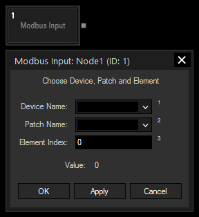
The Modbus input node allows you to retrieve the current value of a Modbus element. Both elements configured as input or output type can be addressed. The respective Client and patch need to be set up before using this node. For more information please refer to the chapters Modbus Client Configuration and Modbus Patch Configuration. In case, you use elements that contain data in the FHPP format, please use the other input node Modbus FHPP instead.
Modbus values can also be retrieved via scripting, as described in the chapter Using Modbus.
This node can be found under Nodes > Input > Devices > Modbus Input

Device Name:
Select the Client device from the drop-down.
Patch Name:
Select the patch from the drop-down.
Enter the index of the element you would like to retrieve the current value from. Please note that the index starts with "0" for the first element. If you have specified names for your elements in the patch configuration, you can as well enter the element's name instead of the index.
With Widget Designer version 6, all nodes support so called node commands. Node commands access functions (i.e methods) from a node and / or set a parameter (i.e. property).
Enter "node", followed by the according ID and a dot and a list will pop up showing all available commands for the node. For instance, Node1.TintColor.SetRGB(125,0,255), colors the node in purple.
In addition, the node properties with a parameter ID (the small superscript number) can be edited via the command Node1.SetParam(ID,new Value) or WDNodeSetParam(NodeID,ParamID,Value).
The Node generates the following output:
- Value (as integer)