Loading...
This chapter explains the current hardware of the NET Link. Please see the introductory chapter for other information and discontinued versions.
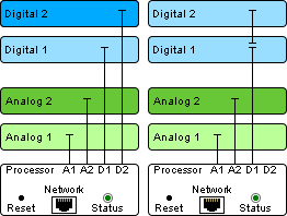
 The dimensions for the base unit are: H: 85mm, W: 172.1mm, D: 121mm. It is 4 slots high. The modules are mounted horizontally. Inherently, the housing comes with one processor unit (2 slots high) that cannot be removed. Hence, there is space for two custom boards that you may choose from eight available board types, each 1 slot: analog / digital and input / output ones. The NET Link is powered with 24V (note that the first version was powered with 12V!) . The AC adapter has an input of 100-240V, max. 2A and an output of 24V, 3.75A via a 4pin-XLR plug. |
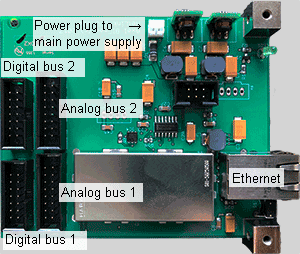
 - a network plug with a network adapter that can be set to any IP address and port number - a "Reset" button to apply the default IP address (192.168.178.222), subnet mask (255.0.0.0 and 5000). To reset the device, hold the reset button down whilst recycling the NET Link, i.e. re-connecting the XLR power plug at the back. - a "Run" LED indicating the status of the unit. The green LED blinks once a second if everything is alright and net work packages are send correctly. If the flashing is slower, the processor unit does not perform properly because network packages can not be send in the expected way. This could be caused by a faulty network environment like cables, switches or IP settings. Please check the status after approx. 100 seconds after establishing the communication between the NET Link and Widget Designer. In addition it manages the connected input / output boards. The processor has four connectors: A1, A2, D1 and D2, available for the connection to the boards. A1 and A2 can be connected to one analog board each. Currently there are only analog input boards available. In other words one processor can be connected to max. two analog boards. D1 and D2 can be connected to digital boards. There are input and output boards available. A digital board has a connector itself to be linked to another board. The daisy chained boards must be of the same type (input or output) and in theory they must not exceed the maximum number of 16 but only two boards fit into the base unit. The advantage of daisy chaining the boards is that switching relays is absolutely in sync whilst switching relays on D1 and on D2 could have a very small delay. So, if you have one input and one output board, you have to connect them to D1 and D2. If you have two input boards or two output boards you can either connect them in the same way (to D1 and D2) or to only one connector and daisy chain them. |
Each board is depicted and described in detail in the next chapter. As well there are examples in which application they can be used.
Analog boards - Input modules
- Calibration Fiber Input
- 0 - 5V Input
- 0 - 10V Input
- 0 - 5V Sensor Input
Digital boards - Input modules
- 12V Relay Input
- 24V Relay Input
- Encoder Input
Digital boards - Output modules
- 48V AC / 30V DC Relay Output
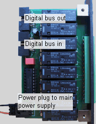
Every board is 1-slot-wide. As explained above they are connected either to the processor unit itself or to a preceding board. In addition it has a power connection plug.

