Loading...
This chapter explains the software settings for controlling the NET Link and getting information from it. Please see the introductory chapter for other information.
Software-wise the NET Link is included in the Widget Designer. The communication between WD and the device is based on an ethernet connection, not USB.
Nodes > Input > Devices > ... or Nodes > Output > Devices > ...
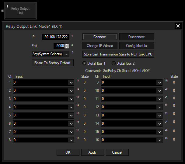
Relay Output node: receiving information from other nodes and controlling the connected NET Link, if it is mounted with (digital) relay output boards
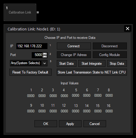
Calibration Link Input node: receiving information from the connected Calibration Link or NET Link with analog input board for fibers; values are transferred to other nodes; the Calibration Input works with the tool "Projector Calibration Manager"
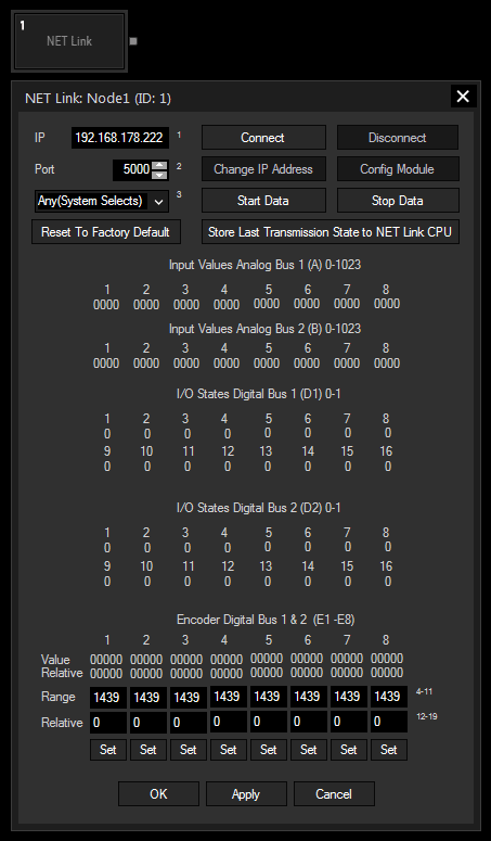
NET Link Input node: receiving information from the connected NET Link (or Calibration Link) according to the input boards and transferring this information to other nodes
All nodes are controllable with node commands. Simply start a script with "Node1." for example, and Widget Designer will offer available commands. Using them, the NET Link input node turns into an output node as well. For instance, this command closes a relay. Node2.SetRelayDigitalBus1(ID,State)
  |
 |