Loading...
This chapter explains the available boards for the NET Link and shows examples how to use them. Please see the introductory chapter for other information.
Currently there are only analog input boards available, no output ones. Each board has 8 galvanically isolated connectors. They detect the incoming voltage in specific, gradual steps providing detailed data information from the connected sensor. Software-wise this is expressed through a value range from 0 to 1023. An application would be a light sensor controlling automatically the brightness of the projection. Principally it is like in the below depicted example with the buzzer, only that the buzzer's place is taken by the sensor and that the switch closes gradually instead of open / close.
Please find below a list with all available input modules:
 8 fiber connectors for single-core (!) fiber cables with a diameter of 0.98mm²
|
 8 connectors, galvanically isolated |
 8 connectors, galvanically isolated |
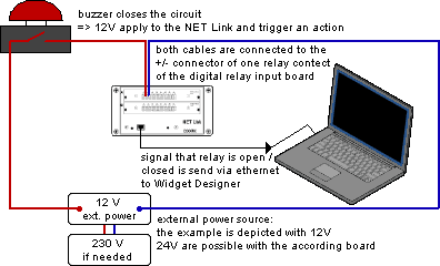
 There are two digital input boards: one for 12V and one for 24V. Both have 8 galvanically isolated connectors. They detect the incoming voltage in two steps and provide the information, whether the connected sensor is in On- or Off-mode. Software-wise this is expressed through the two values 0 and 1. If the voltage exceeds 80%, the status switches to "On". If the voltage falls below 20%, it switches to "Off". An exemplary application would be a buzzer that triggers a cue.  - 12V Relay Input 8 connectors, galvanically isolated phoenix plug (for two laces per connector ≤ 2.5mm²) maximum voltage of 12V 30kΩ input impedance "On" or "1": > 9,6V "Off" or "0": < 1,2V external power source for sensors is needed operating lifetime: 100 000 switchings could be used for GPI In if 12V are used; for the commonly used 5V, the analog input would apply - 24V Relay Input |
 4 x 5-pin M12 connectors, with following pin assignment for female connector The Encoder Input Board replaces the discontinued Sensor Link device and is suitable to be connected to rotary sensors, e.g. encoders from Wachendorff (www.wachendorff.com) or another company. Whilst the Sensor Link could handle 7.000 steps per second, the new board can handle roughly 100.000 steps and thus can be connected to encoders that are 15 times faster or more precise. If you for example choose an encoder with 4096 steps per rotation the board input could process 1480 rotations per minute, which equals nearly 25 rotations per second. If the encoder turns faster (or another encoder with a higher resolution is used) the board will lose track of the absolute step count of the encoder. This leads to drifting and wrong values. Due to the output circuit data of the encoder (which is "HTL" in Wachendorff sensors) there are four shoulders for one circuit. That means for our example: An encoder with 1024 cycles (or "PPR" = Pulses per Revolution, or "LPR" = Lines per Revolution) generates 4096 steps per second at one full rotation per second. This can also be called "CPR" = Counts per Revolution. To calculate the precision of the encoder, we need to divide 360° by 1024 PPR which results in a 0.35° rotation angle. To summarize the result of the two calculations above: the higher the resolution (steps) of the encoder, the less rotations per second will be possible to be processed in the Encoder board flawlessly but a finer resolution can be reached. Higher frequencies are more likely do lead to issues and shorter cable length. A cable length of 20m is roughly the maximum when operating at full frequency of 100.000 steps/s, while longer distances can easily be handled by reducing the data. Hence, it does not make sense to choose an encoder with the highest resolution available but one with the resolution you really need and benefit from optimized data processing and cabling. Please see the chapter Encoder Inputs E1 and E2 from the Sensor Link chapter to see how to order a suitable Wachendorff encoder. Bear in mind, that the resolution from the board is 100.000 steps. If you would like to use encoders from another company, please contact our support team. In general a sensor must meet these requirements: - Encoder input voltage: 10-30V via 2 pins as depicted above - Encoder signal output: - must be via 3 pins as depicted above (e.g. ABC, ABN, ABM) - "on" state must have more than 6V - HTL signal (TTL only with above requirements regarding voltage)
|
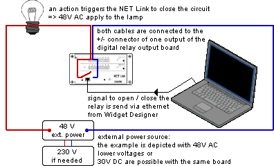
 Currently there is one digital output boards. It has 8 galvanically isolated connectors / contact closures. They close the circuit at the software's command.  - 48V AC / 30V DC Relay Output 8 connectors, galvanically isolated, polarity can be reversed phoenix plug (for two laces per connector ≤ 2.5mm²) maximum voltage of 48V AC or 30V DC and maximum ampere of 4A 30kΩ input impedance contacts are normally open (NO) external power source is needed could be used for GPI Out if external voltage is used as commonly done in broadcast environment; for other application, an external power source must be considered somehow |