Loading...
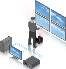
 The AirScan is a laser scanner device that measures distances in two dimensions. Thus, it allows for optical and contactless detection of objects or persons or just their hands. It can be used for any touch-less interaction with a display or a projected touch surface. In Widget Designer, our interactivity software, the AirScan is available as an optional input device and can be setup using the AirScanManager. It is possible to read up to 24 input points and use them for various applications within Widget Designer or Pandoras Box. |
 |
Please note the following restrictions to ensure correct usage and measurement readout:
- Due to its IR laser technology, the AirScan device itself should not be exposed to direct sunlight or direct tungsten lighting as this would distort the correct readout of the sensed data.
- Physical contact with the front cover of the sensor is to be avoided. Note that even a slight movement of the sensor affects the measurement values.
- If the AirScan is (partly) mounted into a wall or exhibition stand, make sure that the sensor (to be exact, the glass window) is not covered and the entire interactivity area is free.
- If a protective housing is provided for the sensor, the detection must not occur through additional window material (plastic, glass, etc.).
- Vapors, smoke, dust and all particles visible in the air could affect the measurement values.
- Glass and highly reflective materials such as mirrors could falsify the measurement value.
- Avoid large temperature fluctuations.
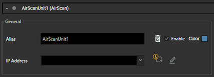
When using the AirScan unit (AirScan Legacy), users can use the 'Auto Discovery' feature. This helps the user select from present devices and apply the respective IP Address.
It also helps to find AirScan Legacy instances that are configured to be in a different network (segment) that could otherwise not even be connected.
This way users also have the option to change the IP Address of the respective device to be in the scope of the production network (address range) so that the device can communicate with Widget Designer.
Precondition for autodiscovering AirScan units (AirScan Legacy) needs WinPcap or Npcap installed. If this precondition is not met, the Auto Discovery icon displays an exclamation mark and gives the following message: "Setting network details is disabled because the machine is missing WinPcap. Install WinPcap and restart the application in order to use this feature."

Ambient temp. (operation/storage) -0°C … +50°C/-20°C … +50°C
Weight: 2.3kg
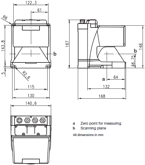
Product Size (WxHxD): 141mm x 167mm x 168mm
Measurement data transmission: 100MBit/s
Measurement range: 0-65m (recommended distance: 0-10m)
Angular range: max. 190°
Angular resolution: 0.36°
Scanning rate: 50 scans/s or 20ms/scan
Wavelength: 905nm
Pulse Duration: 3ns
Voltage supply: +24VDC
Overcurrent protection: fuse 2.5A
Current consumption: approx. 1A
Power consumption: < 75W


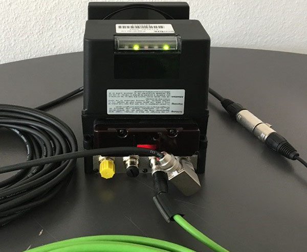
Rear View with scanning direction going up: connections and LED indicators from left to right
Connectors |
|
|---|---|
M12 plug / Connector1 |
For special applications and not to be used. |
M12 socket / Connector2 |
For special applications and not to be used. |
M12 socket / Connector3 |
This is the 100MBit/s Ethernet socket to connect a network switch or a computer. Use the supplied Ethernet cable with the 4-pin D-coded connector for the AirScan and the RJ-45 connector for the switch or computer. The interface is configured with the IP address labeled on your device and the subnet mask is 255.255.255.0. Both can be changed from within the 'General' settings of the unit. |
M16 plug / Connector4 |
This is the power plug. Connect the supplied power cable with the 14-pin M16 connector to the AirScan and the XLR male connector to the XLR female connector of the low voltage power supply. Then connect its power cord. Note that the device powers on automatically and that there is no dedicated power switch. |
Ethernet status indicator |
|
|---|---|
Left, red LED 1 |
Ethernet system ready |
Middle, red LED 2 |
Ethernet connection present |
Right, red LED 3 |
Ethernet data transmission active |
General device status indicator |
|
|---|---|
Leftmost, |
- slowly (1Hz) flashing: internal warning message (e.g. due to soiled sensor cover) |
Green LED 2 |
Detection field up to 30m is free |
Red LED 3 |
Detection field up to 30m is occupied |
Yellow LED 4 |
Detection field over 30m is occupied |
Rightmost, |
Sensor functions active |