Loading...
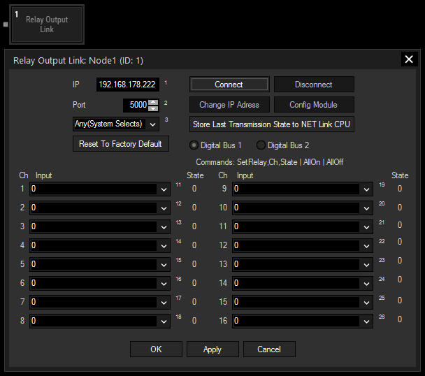
The Relay Output Link node allows to communicate with the NET Link equipped with output boards. Please see more information in the chapter covering the NET Link.
The node configures the device and sends commands to it, for instance to close a contact.
The NET Link Input node might also be of interest for you.
This node can be found under Nodes > Output > Devices > Relay Output Link

IP and Port:
Enter the correct IP address and port from the NET Link's processor or from the Calibration Link.
Reset To Factory Default:
This buttons resets the above settings in the Widget Designer interface. To reset the device itself (to the IP address 192.168.178.222 and the port to 5000), hold the "Reset" button down whilst plugging the power into the device. Release the button again.
Connect / Disconnect:
Before starting to communicate with the device, for instance receive data, the node must be connected to the device. The connection itself consumes no performance.
Change IP Address:
This button opens a new dialog whereto you may enter another IP address and port for the device. Power-cycle the device to apply the changes.
Config Module:
A NET Link / Calibration Link is configured by us as you have ordered it. However, if you have changed some input / output boards, the processor must be configured in terms of giving him the information which boards are connected to it. Click the "Config Module" button to open a new dialog where you may choose the according boards per processor connection. Find more details in the NET Link hardware chapter.
Start Data / Stop Data:
As soon as data is processed via the network from the device to Widget Designer, performance is drawn.
Store Last Transmission State to NET Link CPU:
Click this button and power-cycle the device if you wish that it remembers whether it should (not) send data as soon as it is powered up.
Select here the digital bus the node is supposed to control
Channel, Input list and State:
First, connect an Input node or Filter node to the Relay node to provide the information "0" or "1". Then open the Item Properties and choose the incoming source data for the channel you would like to control. The "State" informs you about the current state of the what the incoming signal. "0" leaves the contact open, whilst "1" closes it.
With Widget Designer version 6, all nodes support so called node commands. Node commands access functions (i.e methods) from a node and / or set a parameter (i.e. property).
Enter "node", followed by the according ID and a dot and a list will pop up showing all available commands for the node. For instance, Node1.TintColor.SetRGB(125,0,255), colors the node in purple.
In addition, the node properties with a parameter ID (the small superscript number) can be edited via the command Node1.SetParam(ID,new Value) or WDNodeSetParam(NodeID,ParamID,Value).
The Relay Output Link node additionally provides specific node commands for directly interacting with the node settings. For instance, Node1.StartData will execute the function automatically without the need of opening the Configuration dialog and clicking the according button manually. Node1.SetRelay(1,1) will set the first channel to the state "1".
The following additional function commands are available for the Net Link Generic I/O node:
- AllOff
- AllOn
- ChangeIp
- Connect
- Disconnect
- GetConfig
- SetConfig
- SetRelay
- StartData
- StopData
- StoreLastTxMode