Loading...
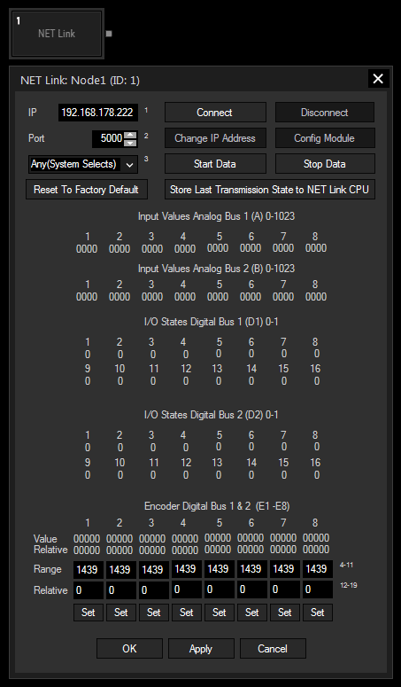
The NET Link Input node allows to communicate with the Calibration Link or a NET Link equipped with input and / or output boards. Please see more information in the chapter covering the NET Link.
On the one hand the node receives information send from available inputs, hence, it provides this data to other nodes in Widget Designer. On the other hand, it allows to configure the device and send commands to it. In case of output boards, a contact closure can be commanded through this node.
The Calibration Input node, the Relay Output node and the tool "Projector Calibration Manager" might also be of interest for you.
This node can be found under Nodes > Input > Devices > NET Link - Generic I/O

IP and Port:
Enter the correct IP address and port from the NET Link's CPU or from the Calibration Link.
Specify here the NIC you want to use for communication with the NET Link.
Reset To Factory Default:
This buttons resets the above settings in the Widget Designer interface. To reset the device itself (to the IP address 192.168.178.222 and the port to 5000), hold the "Reset" button down whilst plugging the power into the device. Release the button again.
Connect / Disconnect:
Before starting to communicate with the device, for instance receive data, the node must be connected to the device. The connection itself consumes no performance.
Change IP Address:
This button opens a new dialog whereto you may enter another IP address and port for the device. Power-cycle the device to apply the changes.
Config Module:
A NET Link / Calibration Link is configured by us as you have ordered it. However, if you have changed some input / output boards, the processor must be configured in terms of giving him the information which boards are connected to it. Click the "Config Module" button to open a new dialog where you may choose the according boards per processor connection. Find more details in the NET Link hardware chapter.
Start Data / Stop Data:
As soon as data is processed via the network from the device to Widget Designer, performance is drawn.
Store Last Transmission State to NET Link CPU:
Click this button and power-cycle the device if you wish that it remembers whether it should (not) send data as soon as it is powered up.
Enter the encoder's amount of steps. If the encoder provides 1440 steps, enter 1439 because the counting starts with zero.
Enter zero to reset the relative step count for the current encoder position or enter an offset value.
Confirm your Range and Relative Values with "Set".
With Widget Designer version 6, all nodes support so called node commands. Node commands access functions (i.e methods) from a node and / or set a parameter (i.e. property).
Enter "Node", followed by the according ID and a dot and a list will pop up showing all available commands for the node. For instance, Node1.TintColor.SetRGB(125,0,255) colors the node in purple.
In addition, the node properties with a parameter ID (the small superscript number) can be edited via the command Node1.SetParam(ID,new Value) or WDNodeSetParam(NodeID,ParamID,Value).
In addition to the general commands, this nodes provides specific function commands that can replace pressing the buttons in the Configuration manually. E.g. Node1.StartDate starts data transmission without opening the dialog.
The following additional function commands are available for the Net Link Generic I/O node:
- ChangeIp
- Connect
- Disconnect
- GetConfig
- SetConfig
- SetRelayDigitalBus1
- SetRelayDigitalBus2
- StartData
- StopData
- StoreLastTxMode
- Tx1 - Tx8
The node generates the following output:
- A1 to A8 (0 - 1023) for the first analog bus
- B1 to B8 (0 - 1023) for the second analog bus
- D1.1 to D1.128 (Open = 0, Closed = 1) for the first digital bus
- D2.1 to D2.128 (Open = 0, Closed = 1) for the second digital bus
- Connected