UV Mapper |


|
UV Mapper |
|
UV Mapper |
|
UV Mapper |
|
Loading...
The UV Mapper is a tool within Pandoras Box designed for precise control over texture mapping on two-dimensional surfaces. In its current version, the UV Mapper supports 2D geometries only, making it ideal for applications such as flat surface projections, LED walls, or simple mapping setups.
UV mapping refers to the technique of assigning image content (textures) to geometric shapes. By manually adjusting UV coordinates, content can be projected accurately onto the desired Surface, regardless of its shape or resolution.
This chapter introduces the fundamental concepts of UV mapping, explains the tool's user interface, and walks through typical workflows for creating and editing UV coordinates. The goal is to enable users to efficiently and precisely control the visual representation of their media content.
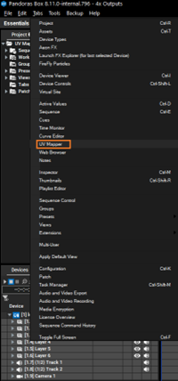
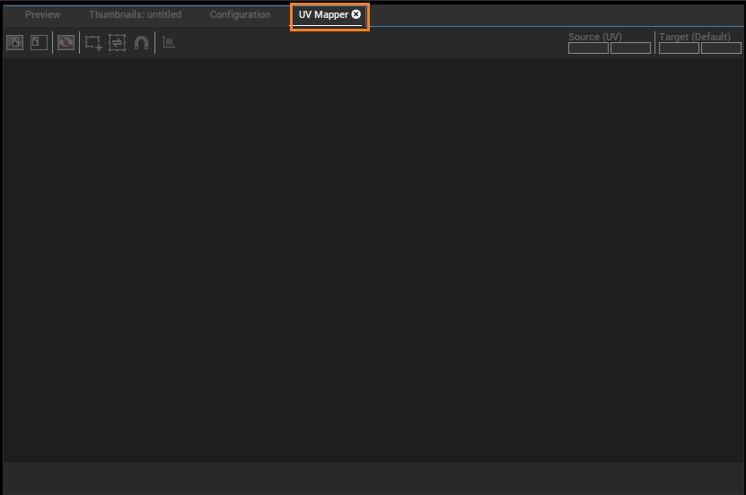
The UV Mapper is an independent feature that is separate from the preview. When selecting UV Mapper from Tabs menu (as shown in the first image), a new window appears in the Preview pane (as shown in the second image).
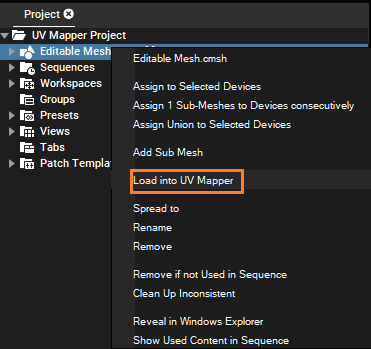
There are two ways to load a mesh into the UV Mapper. Only Pandoras Box editable meshes work with UV Mapper.
Option 1: Right-click Editable Mesh and select Load into UV Mapper. This loads the mesh into the UV Mapper tab. If the UV Mapper is not yet open, it opens automatically and the UV Mapper displays with a loaded mesh.
Option 2: If the UV Mapper tab is already open, for example in the UV Mapper View, drag and drop the mesh directly into the UV Mapper from the Project Tree. The name of the currently loaded mesh is displayed in the middle of the upper button bar.
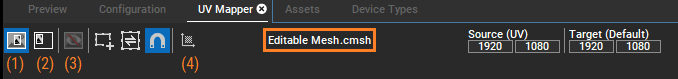
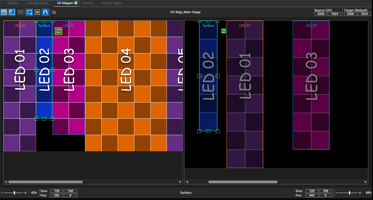
There are two views in the UV Mapper: Source View (labeled 1 in the second image in the Getting Started section) and Target View (labeled 2 in the second image in the Getting Started section).
The Source View corresponds to the input texture and its UV coordinates. This is the default view. Here you can define the regions which have to be remapped. For an easier definition of the source region, you can load a texture per drag and drop into the Source View as a background image. Based on this image, the Source regions, corresponding to the Surfaces in the mesh file, can be positioned for remapping.
The Target View complies to the Target texture. This can simply correspond to the remap on a Layer, or if the Mesh is used on an Output, the size of the Target View corresponds to the Output. Please note that the Output must not be smaller than the size of the Target View. As is possible for Source View, an image can also be loaded in Target View to position the Target regions more easily. This image can be hidden by using the button Hide Target Region Background Image (labeled 3 in the second image in the Getting Started section). In addition, the Target regions are displayed semi-transparently so that you can position them exactly in the background image.
When you toggle both view buttons (1) and (2), a split view appears with the views distributed equally at a 50:50 ratio inside the UV Mapper tab. If a mesh is loaded, at least one mapping region is visible. The number of mapping regions shown corresponds to the number of mesh surfaces. As long as a mesh is loaded, a minimum of one view is shown.
In the UV Mapper button bar, you can define Source (UV) and Target (Default) size. The default size for both is 1920x1080 pixels. You can navigate between the source and target fields using the Tab key and enter the desired values.
When a background image is inserted by dragging and dropping (D&D), the Source or Target size, depending on where it is dropped, automatically adjusts to match the image's dimensions. If the Source or Target sizes have previously been manually defined by changing UV and Default values, the inserted image is resized to fit the defined size. These sizes also display in the asset's inspector of the Mesh file.
If the Source and Target size is larger than the view inside the UV Mapper, you can use the scrollbars to scroll to the area of interest. There are separate zoom bars for Source and Target Views.
As known from zooming inside the Sequence, there are the following zoom options.
- The zoom bar offers + and - buttons which can be clicked once or held down for continuous zoom.
- The slider on the zoom bar can either be dragged or moved with a single click.
- The Zoom level number can be edited by double-clicking or entering a custom value.
- The Zoom level number can be right-clicked to choose a zoom level between 100% and Fit2Tab. Fit2Tab shows the complete Source or Target size with keeping its aspect ratio inside the view.
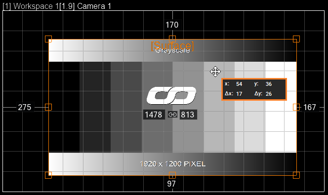
When you hover the mouse over a previously created or already existing region, the cursor changes to a "Move" cursor. If you left-click and drag, the region under the mouse moves accordingly, freely within the boundaries of the corresponding view. The drop action positions the Surface at this point.
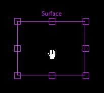
If you hold down the middle mouse button (the scroll wheel), the mouse cursor changes to a hand. This allows you to scroll more easily and quickly. Zooming using the mouse is also possible using "Alt + Mouse Wheel".
The content of the Target region automatically adjusts when the Source region is moved over the texture. Moving the Target region does not change the remapped content, only the Target position to which the remap is applied. To save the remap in the mesh file, Calculate UV Coordinates (labeled 4 in the second image in the Getting Started section). Only moving the Source and Target region is not enough.
The size and therefore the aspect ratio of the Target can be changed independently of the Source region.
As soon as a region or Surface is selected in the UV Mapper, this Surface also receives the highlight in the Project Tree and thus all Surface information displays in the Inspector. It works in the same way if a Surface gets selected in the Project Tree. The Inspector shows its information, and this Surface is directly selected for editing inside the UV Mapper.
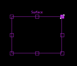
As already known from Workspace or 2D Mesh Editing Mode, the surfaces have control points for 2D editing, such as scaling or rotation. When you move the mouse over these control points, the cursor changes to a "scale" cursor. If you left-click and drag, the size of the region changes. The size of the region adjusts independently of the correlated region. However, when resizing the Source region, the contents of the Target region is adjusted (compressed or stretched) accordingly.
Similarly, when resizing the Target region, its content adjusts while the content of the Source region always remain unchanged and maintain its native size.
The UV Mapper does not allow any region outside its boundaries. If a handle reaches the edge of the Source or Target size, it prevents further scaling or rotation beyond that point.
To scale a region while maintaining the aspect ratio or perform symmetrical scaling around the center of the region, use the commands provided below:
- Scale + Shift: Keep aspect ratio while scaling.
- Scale + Alt: Scale symmetrically around the center of the region.
To position or adjust the surfaces accurately, use the cursor keys provided below:
- Shift + Cursor keys: Shift the entire surface by 1 pixel.
- Shift + Alt + Cursor keys: Shift the entire surface by 10 pixels.
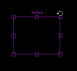
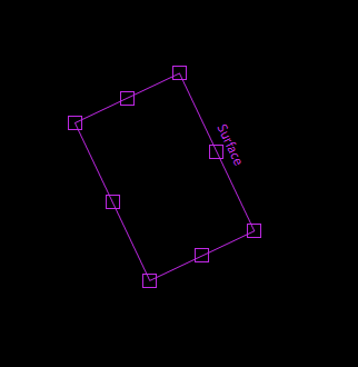
For rotation, only the corner control points of the region can be used. Around the corner control points, there is an area where the mouse pointer changes to the "Rotate" cursor. If you left-click and drag, the region rotates accordingly under the mouse cursor. During rotation, the region snaps to integer multiples of 45 degrees.
The regions in the Source and Target rotate independently of each other. If the Source region is rotated, the content of the corresponding Target region adjusts accordingly, but the Target region itself is not rotated. However, when the Target region is rotated, neither the content of the Source nor the content of the Target region changes, only the Target region itself is rotated. For rotated regions, the name is also rotated along with the regions, so that the orientation of the region is recognizable.
The size, position, and rotation of the Surface or region can also be edited in the Inspector. When you adjust a Surface's rotation, the Inspector restricts rotation values to a range of -180 to 180. Values below "Default" defines the Target region. Values below "UV" defines Source region values.
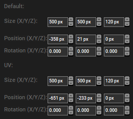
Modifying the size, position, and rotation values in the Inspector updates the corresponding Surface or region in the UV Mapper. The size and position of the selected Surface or region are additionally editable inside the input field below the Source and Target Views. Once you enter one of these input fields, you can change the field using Tab from the keyboard.
Please see submesh inspector for more information.
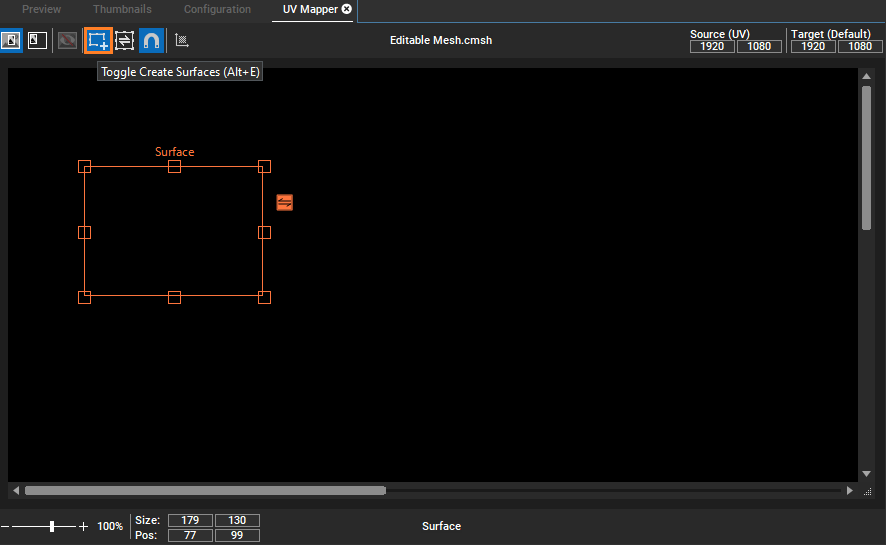
A toggleable Surface Creation mode  is located next to the "Toggle Source and Target View" button, allowing users to create Surfaces or also called rectangles. Once the mode is enabled, left-clicking and moving the mouse up or down in an empty area inside the Source or Target creates a rectangle which is defined by the selected area. The shortcut [Alt + E] toggles the "Create Surface" button.
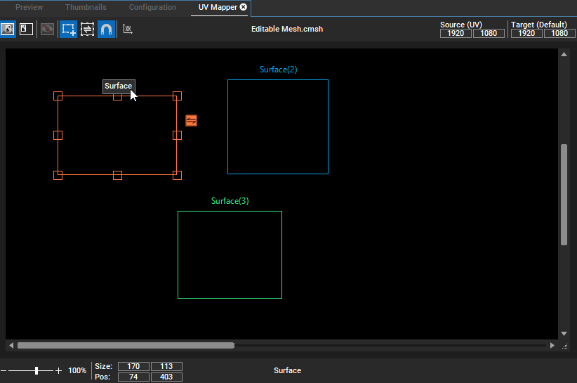
You can create multiple regions within the UV Mapper. Creating regions generates new Submeshes/Surfaces. The default name for each region is based on the Submesh name ("Surface(n)"). By double-clicking the region or Surface name inside the UV Mapper, the user can change it.
The name of the selected region or Surface displays at the bottom edge of UV Mapper.
The UV Mapper enables the multi-selection of regions or surfaces. You can delete selected regions using the "Del" shortcut on the keyboard, and this change is synchronized with the Inspector and the Project Tree. The scale, move, and rotate functions behave similarly after selecting a region to how they work in Workspace mode. Deleting surfaces from the UV Mapper cannot be undone.
A new region can be created in both views: Source and Target. For each newly created region, an identical region is automatically created in the corresponding view. The corresponding region is positioned and sized with the same values in its view.
The content of the Source region is reflected in the Target region directly. Frame colors are automatically assigned for each pair of rectangles.
Created regions cannot be resized beyond the defined size of Source or Target view. If you attempt to resize a region, it automatically adjusts to the minimum size required to maintain this constraint. The following warning message appears in the status bar to notify you of this adjustment: "Region Size must be large enough to contain the entire mesh Bounding box."
Similarly, if a texture is loaded onto an unlocked UV Mapper region and it is larger than the editing canvas, you see the same warning message.
If a mesh contains surfaces that have been transformed into a 3D space through rotation or changed FFD or Vertex modifier in Mesh Editing mode, it is prevented from loading into the UV Mapper, accompanied by a warning message. If a mesh is already actively loaded in the UV Mapper and it becomes a 3D object, the UV Mapper is blocked from editing this mesh and the mesh name displays in red to indicate this.
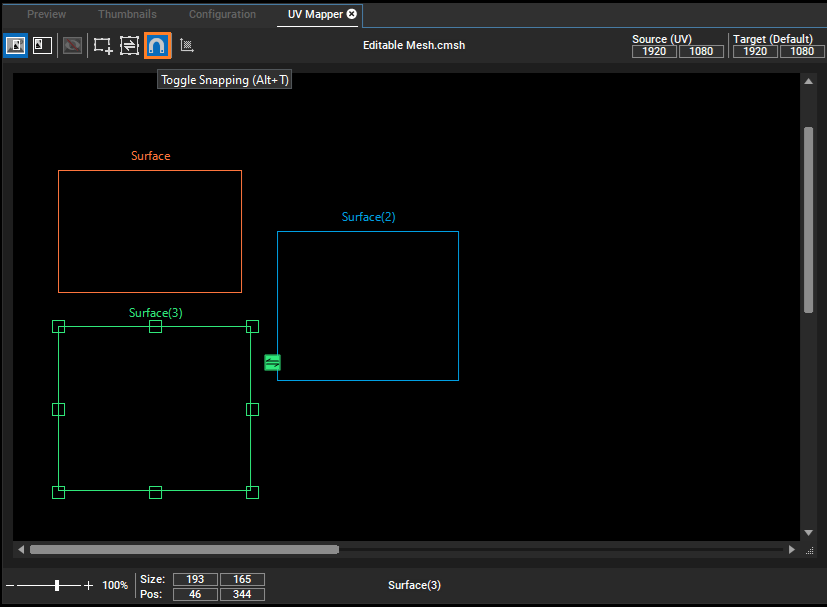
To make it easier to position regions, snapping to other regions is activated for them by default. If you want to deactivate snapping, use the button Toggle Snapping or the shortcut [Alt + T]. When snapping is enabled, the edges of regions automatically snap to other regions and view borders. For rotated regions, their four control points align with each other during snapping. This behavior applies when moving, scaling, or rotating shapes, and only affects the active page—whether it is the Source or Target. In the UV Mapper, snapping occurs at a consistent distance from objects, regardless of the zoom level.
By default, the Source and Target regions are synchronized in size and position at the time of creation. To keep them consistently the same size, you can enable "sync mode". When active, any size adjustments made to one region automatically applies to its sibling. This mode can be toggled using the shortcut [Alt + R].

When the sync mode is toggled off, a small button appears next to the region (see image below), allowing you to manually synchronize its size with the sibling region when selected. Please note that you can use this button to get the size information from the other view, not to send the size.
The remap information is only saved in the mesh after the UV coordinates have been calculated using the "Calculate UV Coordinates" button  . Once the UV calculation has been performed, the remap is saved in the mesh. Now this mesh can be used for a UV remap on a Layer or an Output.
If the mesh should be used on a Layer, then, as with other meshes, it is dropped into a container with a texture. Another option is to use the mesh as a permanent remap on a Layer. To do this, the mesh must be dropped onto the Layer in the Device Tree as an active value. For further details, see Helpfile - Pandoras Box 8.11.0 & Widget Designer 6.6.2.
When a mesh with UV Mapping Meta Data is assigned to an Output Layer, there are four scenarios that can occur:
1.If the Source Size matches the Camera Size (assigned to the used output) and the Target Size matches the real adapter resolution (Output), the mesh is successfully assigned.
2.If the Source Size matches the Camera Size but the Target Size differs from the real adapter resolution (Output), a popup window appears notifying the user that the Output Size does not match the Target Size and provides three options for the user to choose from.
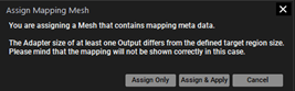
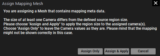
3.If the Source Size does not match the Camera Size but the Target Size matches the real adapter resolution (Output), a popup window appears notifying the user that the size of at least one camera is different from the source region and provides three options for the user to choose from.
4.If the Source Size does not match the Camera Size and the Target Size does not match the real adapter resolution (Output), a popup window appears notifying the user of the discrepancies between the source and target sizes and provides options for the user to take action.

For cases 2, 3, and 4, there are three options available for how to proceed:
Assign only |
The mesh is assigned to the Output Layer leaving the Camera values unchanged. |
Assign & Apply |
The mesh is assigned to the Output Layer and the corresponding data is applied to the Camera. Changes are reflected in these options in the Inspector, depending on the exact mismatch. Camera Aspect Ratio—Adopt Output Aspect Ratio is disabled and the width and height is set. 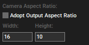 Composition Render Target Size—Adopt Output Viewport Size is disabled and the width and height is set. 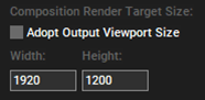 |
Cancel |
This option cancels the process. No mesh is assigned to the Output Layer. There are no changes for Camera values. |
If these actions are not canceled, active values arise. These active values can either be saved as containers or made inactive so they are applied to the entire sequence.