Loading...

Folder and File ID
Set numeric virtual file and folder IDs for DMX, PB Automation and Widget Designer remote control and thumbnail exchange.
Segments
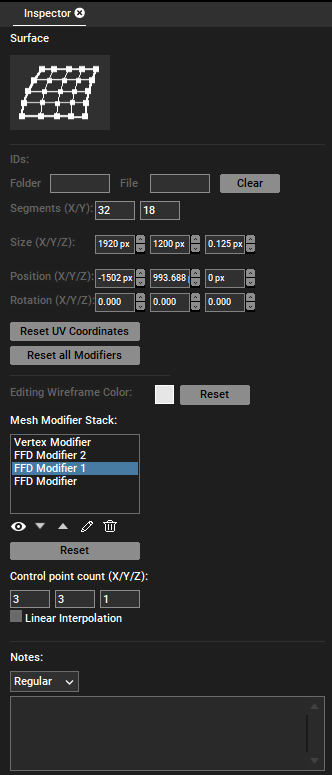
Here you can change the horizontal and vertical Segment count of a Mesh which is known as Mesh points in the Warper. The advantage of many Segments is that you can warp with more detail whilst the disadvantage is that this takes more time. If you project on a surface that is only partly complicated whilst other parts are more plane and would allow fewer Segments, the Planar or Perspective UV Mapping Mode might offer an alternative solution as it allows to assign a UV map from one source to multiple meshes.
Note that you should adjust the Segment count before warping as any change will erase.
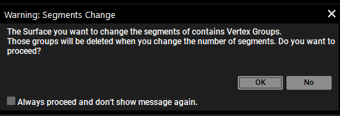
If the number of segments of a Sub Mesh is changed, all associated Vertex groups are automatically deleted.
When this happens, a warning message will be displayed indicating that if the segment is canceled, the change of the segments should not be carried out.
The warning can be deactivated by selecting the "don't show message again" checkbox.

Size, Position and Rotation
All these settings influence the mesh before it is even assigned to a Layer. Enter pixel values for "Size" and "Position" and degrees values for "Rotation". Note that working in the Sub Mesh Mode within the Mesh Editing Mode in the Preview changes these values as well.
Reset UV Coordinates
This resets the UV Coordinates and applies the default UV map. You can change the UV map with the Planar or Perspective UV Mapping Mode from the Preview.
Reset all Modifiers
This resets the FFD and Vertex Modifier in case you have moved FFD or Vertex points using the according modifier in the Mesh Editing Mode from the Preview.
Editing Wireframe Color
If you click on the colored box, a dialog opens were you can choose another color for the mesh which is visible in the Mesh Editing Mode when the FFD or Vertex Modifier is selected. This is especially useful if you need to overlap several meshes. Coloring one red, and the other green for example will result in yellow lines if both meshes overlap (partly).
The Reset button assigns a light gray color again.
Mesh Modifier
You can select either the Vertex or the FFD Modifier and click the below buttons.
The "Reset" button resets all points of the selected modifier to the initial default position.
In the Inspector, under Mesh Modifier stack, the eye icon can be used to switch on and off whether the selected FFD Modifier is applied or not. With the arrow up or down button, you can change the order of the self-created FFD Modifier inside the Mesh Modifier stack. Keep in mind that this positioning corresponds to the render order. The order of the modifiers is hierarchical, with those at the top applied over those below. Additionally, the Vertext Modifier is fixed at the top of the list and cannot be rearranged.
In addition, the modifiers can be renamed by selecting the pencil icon or removed by selecting the garbage can icon. This will be reflected in the Mesh Selection tree. The Vertex Modifier cannot be deleted, nor can the standard FFD Modifier without Vertex Group.
In the Sub Mesh Inspector, it is possible to activate linear interpolation for FFD Modifiers in addition to specifying the number of control points. By checking "Linear Interpolation" option, the vertices between two control points of the modifier can be interpolated linearly. If "Linear Interpolation" is deactivated, a Bezier interpolation is used.

When you change the number of vertices in a Mesh, all the FFD Modifiers that are based on the FFD group will be removed. When you select FFD Modifier along with Vertex Modifier, the control point counts disappear. From the Mesh modifier stack, you can select multiple FFD/Vertex Modifier and can update the control point count and linear interpolation count.
If you select the FFD Modifier, you can change the "Control point count" below the list. The according count for the Mesh "Segments" can be found at the top of the Inspector.
Notes
Please see the File Inspector.