Loading...
To create a node
a) open the node menu from the main menu bar...
b) click on the node symbol in the toolbar...
c) right-click anywhere in the empty main background and open the Nodes menu there...
c) use the keyboard shortcut [Alt + N] whilst you are in the edit / move mode ...
...and choose the desired node. The nodes are attributed to five node types: Inputs, Filters, Outputs, the more advanced Scripts and Interactions and additionally the customizable Composite Node. Some categories are sub-divided once more in order to make it easier and faster to find the nodes you are looking for. The table on the previous page lists all categories and nodes. If you know how your node is called, it may be faster to click on "Search" and start typing, the drop-down will suggest possible nodes to you.
Input nodes provide numeric or text based input values.
For example the Mouse or Joystick Input node provides you with an X&Y value.
This value might be related to screen coordinates based on your local display resolution 1920x1080.
Filter nodes are used between Input and Output nodes, they recalculate the input value.
For example you might want to map the mouse motion to the 16bit value range of a layer in Pandoras Box between -8 and +8.
To resolve this you simply connect a Range Filter node to the Mouse Input and tell the Range Filter to recalculate the range from {0 to 1023} to {-8 to +8}. This is all it takes, this example is described step-by-step in this short tutorial.
Output nodes are used to send values out.
They receive an incoming value (from Input nodes directly or Filter nodes) and -according to their category- send them to another external device, or to Pandoras Box, or to a widget used in Widget Designer itself.
For example, you if you connect a Range Filter node with a Layer Output node, you can set up in the Layer Output node that the Range value should be send to the X Position parameter of a given layer.
Script nodes execute your customized script; they are triggered through a certain action.
They cannot be linked to other nodes, they are stand-alone. One could also say they are a fixed combination of an Input node to several Script Output nodes. This makes them very performance saving. In detail, Script nodes execute directly customized scripts as soon as a chosen action happens within Widget Designer. This can be, for example, a certain ASCII or Byte value coming in through the local COM port. One single Script node would combine one ASCII value with the first script and another ASCII value with another script and so on. Another type of (incoming) trigger can be an Action (e.g. a button is clicked, a fader changes the value etc.) or even a Gesture (e.g. Swipe Up) that is recognized in a tool like the AirScan.
Interaction nodes execute an underlying application that enables to interact with a remote system.
They cannot be linked to other nodes, they are stand-alone. Each Interaction node has a special function that would require a complex node and command combination. For example:
- they send the mouse or touch events happening on the local system to another system, or
- they use the local mouse or touch events to draw on a Canvas Asset, or
- they watch a folder on the local hard drive and add new files to a Pandoras Box project plus append it to a Playlist
Composite Nodes are especially useful if certain combinations of nodes are being used multiple times, for reducing complexity or for distribution of node-based solutions of any kind. As you can create your own customized node containing a composition of nodes and widgets, this feature offers high flexibility.
 |
Once you have chosen a node, the mouse cursor will change to a crosshair icon, telling you that you are in the operating mode called "create mode". Wherever you left-click now, the chosen node is generated. You may click again, to generate a second node from the same type. The small number in the upper left corner is the node`s ID. |
 |
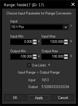
If you want to configure the newly built node, simply double-click it, or right-click on it and choose "Configure Node...". The node's configuration dialog opens up. The left image depicts the configuration of a Range Node. (It is already set up with example values.) Here you can set up the static parameters and everywhere you see a drop-down list you may choose to pick a source node value output or enter a static numeric value into the text field of the combo box directly.
|
 |
In many nodes you will notice little index numbers next to the input fields. These index numbers are important if you wish to remote control a node source or node value via commands from any other element such as a Custom Script Button or external remote or other output script node. This makes the node system very dynamic and lets you design systems that can change their behavior based on specific input parameters and controls. |
  |
To connect two nodes with each other first switch to the edit mode by pressing [F9] (the mouse cursor differs from the standard mouse icon). Now, left-click and drag the source node output pin to the target node and release the left mouse button. The connection between the node is now displayed as a gray line. It is possible as well to connect nodes on different pages.
|
  |
To delete a single connection between two nodes, switch to the edit / move mode and select the Node Connection by clicking on it. The Node Connection turns blue. Now press [Delete] on your keyboard to delete the Node Connection and confirm the upcoming pop up dialog. Multiple connections can be selected with a selection frame (left-click and drag). Removing connections does not reset all node values. Some node parameters are not based on source node values and can be set manually. |
  |
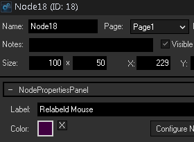
To copy and paste nodes, you have to be in the edit / move mode [F9]. To copy a single node, just click on it or drag a window across it. All Node Properties will also be copied, as long as the Node Sources are copied as well. This means also, that copied Input Nodes will not have any connections attached, in opposition to Filter and Output Nodes which will automatically be connected to the same Input Node(s) as the original. To set up the properties of the node (= the node's look, i.e. Text and background color as well as Protection Settings), In addition to the Config dialog there is also an Item Properties dialog. Right-click on the node and choose the menu entry "Item Properties" or press [Alt + P] whilst having it selected. The left depicted dialog opens up. Now you can change various settings like the text of the node or its background color. The Name is of interest when using the member notation. |