Mesh Marker Mode |


|
Mesh Marker Mode |
|
Mesh Marker Mode |
|
Mesh Marker Mode |
|
Loading...
Using the Mesh Marker Mode is an easy way to align your projection onto any object or screen shape. All you need to do is define some Marker Points on an accurate 3D model, position the Calibration Points on the real projection object or screen, and let the system calculate the correct Camera or Output parameters so that the projection aligns perfectly.
For the Mesh Marker Mode, you must use a Pandoras Box mesh file (.cmsh). If you have 3D objects in other file formats, like obj or fbx, you must convert it into a Pandoras Box cmsh-file through the context menu. For more topics related to the Preview tab, please refer to the introductory chapter.
To start Mesh Marker Mode, follow these steps:
1.Right-click in the Project tab and select Add Editable Mesh.
2.Save it or use the context menu entry Create editable Mesh from Mesh from another 3D object type to convert this file into a Pandoras Box mesh file.
3.Assign the editable mesh to your Layer or Output.
4.Toggle the Preview to the Mesh Marker Mode.
5.Select the Camera or Output you want to calibrate.
6.Select the Layer or Output where the mesh is saved.
Cameras and Output-Cameras
The Mesh Marker Mode features are only visible in the Preview for the selected Camera or Output. If your mesh is stored at a Layer, select the Camera you want to calibrate. If the mesh is stored on an Output, choose the corresponding Output. During the activated Mesh Marker Mode, Marker and Calibration Points are shown at the real Output, so you can position your Calibration Points exactly to the object to which you want to calibrate. Marker and Calibration points only belong to one Camera or Output. This means that if you want to calibrate an object for several projection devices (Cameras or Outputs), you must create separate Marker and Calibration Points for each camera or output.
For camera and preview, see Select Preview: Camera or Output View for more information.
Select Editing Context
In this menu, select the corresponding layer on which the mesh to be edited is saved. If the mesh is positioned on an Output and the Preview is set to this, the corresponding Output Layer is automatically selected.

In Mesh Marker Mode, the "Select" mode (1 in the image below) is activated per default because the first calibration step is to define Marker Points at the mesh vertices. For 3D Objects, a minimum of six Marker Points should be defined.
The image below displays the different functions:
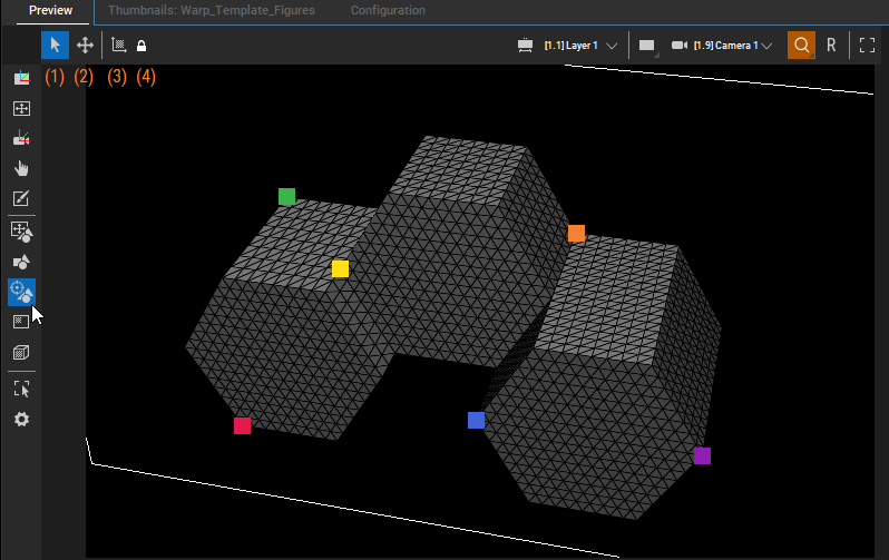
1 |
 |
Select Mode |
This is the default selection in Mesh Marker Mode where you can create and delete 3D Marker Points. A left-click on a vertex of the mesh creates a marker point on this vertex. A left-click on an existing marker point deletes this marker point. For easier handling of 3D objects, it may help to overwrite the global configuration for mesh shading and change the wireframes to triangles. You can also set the global configuration for mesh shading to triangle. While creating the marker points, it makes sense to adjust the preview accordingly (zoom, rotate) so that you can select the correct triangle corners or vertex to be used for calibration. |
2 |
 |
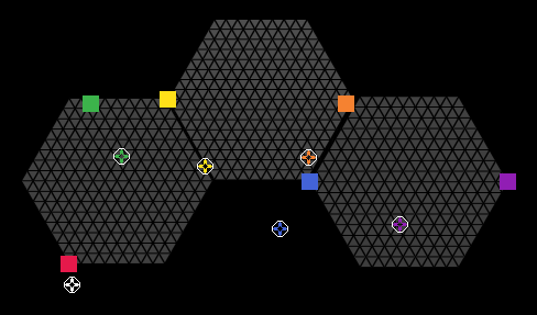
Move Mode |
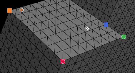 In Move Mode, the corresponding 2D Calibration Points are shown. For every Marker Point there is a Calibration Point in the same color created. If the Calibration Points match the position of the Marker Point, it is displayed as a circle at the top of the Marker Point. Once a Calibration Point is moved by drag and drop, the circle is filled with a crosshair. The Calibration Point, which is currently being worked on, has a white crosshair in the circle. All other Calibration Points, which are not at the same position as the Marker Points, have colored crosshairs in the same color as the corresponding Marker Points. It could be necessary to change the view in the preview while positioning the Calibration Points so that you can grab the right one for calibration. The final positioning of the Calibration Points is then carried out in the projection onto the real object. For fine adjustments, each Calibration Point can also be moved using the cursor keys. As known from the Mesh Editing Mode, you can move the Calibration Point in small steps with "Shift + cursor arrows". "Shift + Alt + cursor arrows" moves the Calibration Points in larger steps. As soon as Calibration Points have been selected, you can use the cursor keys to switch back and forth between all Calibration Points. The system always switches to the nearest Calibration Point in the direction of the cursor key. |
3 |
 |
Calculate Camera Parameters |
 After moving the Calibration Points to the desired location, select the Calculate Camera Parameters to adjust and update the Camera or Output parameters accordingly. If the mesh is positioned on top of a layer, the values should be applied to the Camera which is selected in the Preview. If it is a mesh at the Output, the values are applied to the corresponding parameters of the Output. 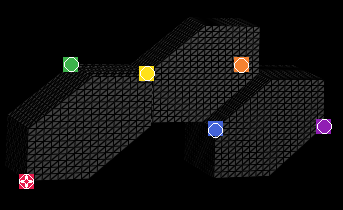 The following Camera or Output parameters are affected by the Mesh Marker Calibration: If the calibration is satisfactory, the active values generated by the calibration should be saved at the timeline. If not checked at the calibration points at your real object, reposition these and recalculate your values. Repeat this until the projection is perfect. If the points align well with the object and you still have bad results, please check the aspect changes in your signal flow. |
4 |
 |
Toggle Continuous Camera Calculation |
When this option is activated, it continuously updates the Camera parameters in real time as you move Calibration Points. The permanent camera calculation is activated by holding down the "Ctrl" key. If the button is only pressed briefly, the calculation is carried out once. |
Zoom and Reset

By default, the Camera Interaction Mode is set to "Zoom". When you adjust the view, such as rotating it, the Zoom button becomes highlighted in orange. Selecting the R button restores the default view and resets any changes made when selecting the "Reset Camera" option from the right-click menu.
The alternative Interaction Mode, "Parameters," is relevant when you are in a Camera or Output view. In this mode, any navigation within the view is reflected in the active Viewpoint and Target parameters. This can then be saved to the timeline. The R button in this mode only resets the parameter changes.

By default, the Preview tab is part of the main user interface. However, you can also choose to work in a maximized Preview. Use the bottom left button or the shortcut [Ctrl + Shift + F] to toggle the Preview tab to a full screen window. All tools, modes, and view options are available in the Button Bar. Use the shortcut [T] to show or hide it. In addition, you can navigate and use the mouse cursor as usual. Each Manager offers this feature.