This chapter explains the Planar and Perspective UV Mapping Mode of the Preview which allows you to assign a UV map directly in Pandoras Box. For other topics regarding the Preview tab please see the introductory chapter. The next chapter covers general mapping questions and is of special interest for mapping beginners.
Per default, a newly created Mesh in Pandoras Box has a 1:1 map meaning that any (existing) deformation in the Mesh also deforms the UV source.
Pandoras Box offers two techniques to apply a new UV map to a Mesh or an object. There is the planar mapping and the perspective mapping for which you can choose the point of view. With both mappings you can "print" the texture on a 2D or 3D Mesh again without taking existing deformation into account.
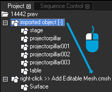
Before you get started with the UV mapping, assign a texture and an Editable Mesh to a Layer. To create an Editable Mesh, right-click in the Project tab and choose "Add Editable Mesh". If you need more than one Surface, right-click on the Editable Mesh and choose "Add Surface" adjust the size using the Surface Inspector or the Mesh Editing Mode.
In case you would like to work with an imported object, simply right-click it and choose "Create Editable Mesh from Mesh". Alternatively you can drag it on a newly created Editable Mesh object as depicted to the left. Afterwards you can remove the "Surface" that was added per default.
Tools for the Mapping Modes
Most buttons are also part of the Mesh Editing Mode, please see this chapter for an explanation. The buttons starting with the stamp icon are explained in the example below.
For the Perspective UV Mapping Mode there is an additional drop-down menu to choose and reset a Reference Layer.
You can follow this example with any Editable Meshes. For now, it should be fine to program in a normal preview but later on you might want to switch to the maximized preview . This button can be found on the left site at the bottom and toggles your Preview tab to a fullscreen window. All tools are available within the Button Bar, that you can toggle with the shortcut [T].Thus, the maximized Preview gives you the best overview, allows to see more details of the image and adjust the UV Source grids better. You can also work with the Mesh Inspector to position, scale and rotate Meshes.
The planar mapping works for all Meshes: 2D or 3D, single or multiple Meshes. This example depicts one Editable Mesh with two Sub Meshes. One Sub Mesh was already deformed with the FFD handles as described in the Mesh Editing Mode.
Per default, when assigning an image (i.e. a texture) it covers the entire (Sub) Mesh and is then deformed along the Mesh lines.
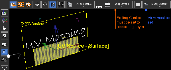
Switch the Preview Mode to the "Planar UV Mapping Mode". Make sure that the view you are working with is correct and that the Editing Context is set to the correct Layer.
Before starting to assign UV coordinates select both Surface UV Sources by clicking into the Preview window and pressing [Ctrl + A]. You should see both names on top of each other, e.g. [UV Source - Surface] and [UV Source - Surface (2)].
Now, press the button "Apply Planar Map to Mesh Bounds". Both UV Source grids are arranged within the limits of the texture. Note that they fit either horizontally or vertically, i.e. the aspect ratio is preserved. The size, position and rotation of the grids does only represent what part of the texture is depicted on the Meshes. The texture itself is displayed in its pixel size.
Press the stamp button to calculate the UV coordinates and toggle into the Layer Mode. Note that the Meshes have their old size, position and rotation but the layer texture is shared differently.
Planar Map to Mesh Bounds
Go back to the "Planar UV Mapping Mode". Select the first button "Sub Mesh Modifier" (shortcut[M]) and then reposition, rotate or scale the UV grids with the according buttons or shortcuts [1,2,3]. If needed you can use the Constraints . With the FFD or Mesh modifier you could influence the UV map in more detail. As the (drop-down)Selection Mode is set to "All selectable" you can transform each grid. If only one Mesh is selected, the other one will be locked.
Custom Planar Map
Always press the stamp button to calculate the UV coordinates. Switch to the Layer Mode to view the final result. Again, the Meshes have their old size, position and rotation but the layer texture is shared differently.
Planar Map (to Fullscreen)
Enter the "Planar UV Mapping Mode" again and select both grids. Select the second mapping button "Apply Planar Map". This time the UV source grids are not scaled to fit the texture but represent the size of the according Meshes. The texture itself is always displayed in its pixel size.
1:1 Map
Last, try the third mapping button "Apply 1:1 Map". Note that the UV source of the deformed Mesh is not deformed. In other words, the texture is first applied to the Mesh and then deformed according to the FFD grid. This was not the case in the other planar maps where the content was rather cut out following the mesh lines.
Perspective UV Mapping Example
In difference to the planar mapping, the perspective mapping allows to influence from where the texture is projected onto the Meshes.
You can follow this example with any Editable Meshes. For now, it should be fine to program in a normal preview but later on you might want to switch to the maximized preview . This button can be found on the left site at the bottom and toggles your Preview tab to a fullscreen window. All tools are available within the Button Bar [Ctrl + T] and thus, the maximized Preview gives you the best overview, allows to see more details of the image and adjust the UV Source grids better.
Scene with 2D plane and 3D wave and a Camera looking from a lower angle.
And the front view of the scene and the view from the Camera.
The perspective mapping works for all Meshes: 2D or 3D, single or multiple Meshes. This example uses an imported object that consists of a background plane and three waves in front of it. The images illustrates the scene. The camera position resembles the position of the audience.
The imported object is converted to an Editable Mesh using the right-click menu in the Project tab.
Switch to the Preview mode "Perspective UV Mapping"
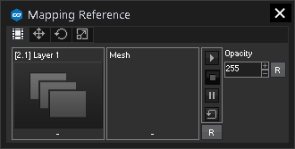
The view automatically zooms out to illustrate the mapping scene with the 3D objects, the camera position and a UV Mapping Reference Layer spanned in the opening angle of the Camera.
In addition, the Parameter Floater opens and shows the Layer's position, rotation and scaling. Per default,. the Reference Layer shares the texture from the Layer you are working with, but if needed you can drag any other media there from the Project tab.
Press the stamp button to calculate the UV coordinates and toggle into the Layer Mode.
Reset the Camera view with the R-button to view the scene again from the saved Camera position which resembles the position of the audience. As the texture was applied from this perspective and spreads over all objects evenly, you can not tell where one object starts or where it is deformed. In other words, the scene looks flat...
... but as soon as you leave this "sweet spot", your perspective changes. The further you go, the less you have the impression to see a seamless image covering all objects.


 Show/Hide hidden text