This chapter explains the views for the Preview. For other topics regarding the Preview tab please see the introductory chapter.
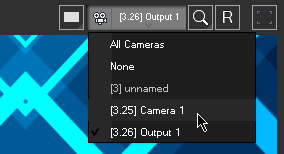
You can load various views into the Preview tab, there are three ways to do so:
- open the upper right drop-down menu "Select Preview"
- right-click in the Preview and select "Select Preview"
- right-click on a Camera or Output layer in the Device tree and select "Load in Preview" The "All Cameras" view is always available but the Camera or Output view(s) depend on the Camera or Output Layers from your Sites / Clients.
|
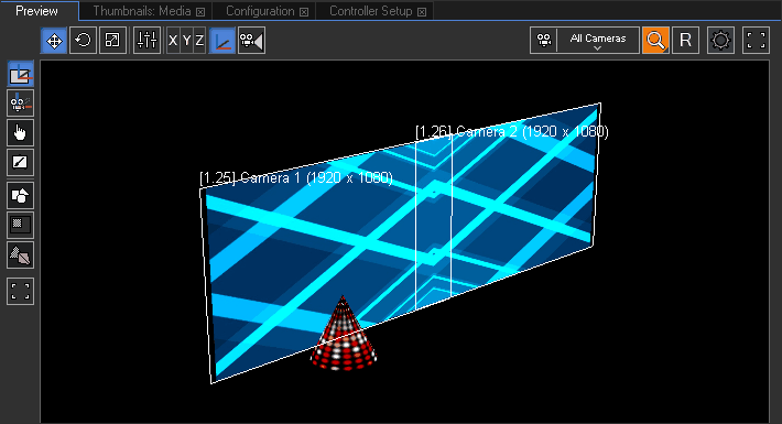 The left image is an example for the "All Cameras" view. It allows previewing all included Sites at once. Furthermore the whole 3D space is shown instead of only the specific area seen by the Site's Camera device. The left image is an example for the "All Cameras" view. It allows previewing all included Sites at once. Furthermore the whole 3D space is shown instead of only the specific area seen by the Site's Camera device.
The next chapter explains how to navigate in the Preview tab.
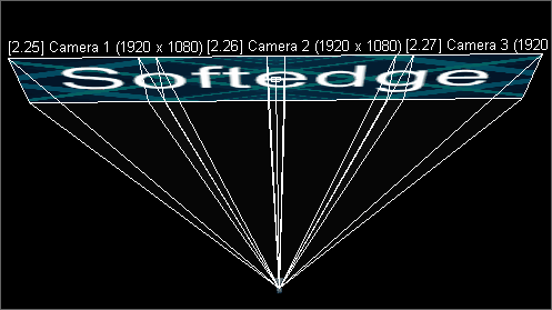
Per default, Camera targets are shown as white rectangles with a label hovering above it naming the Camera Layer and resolution. Resolution and aspect ratio can be changed in the Inspector of the Camera, whilst Camera position etc. can be changed in the Camera Device.
In addition to the rectangle you can toggle more wireframes and handles. This is explained in one of the next chapters: Preview handles and wireframes.
|
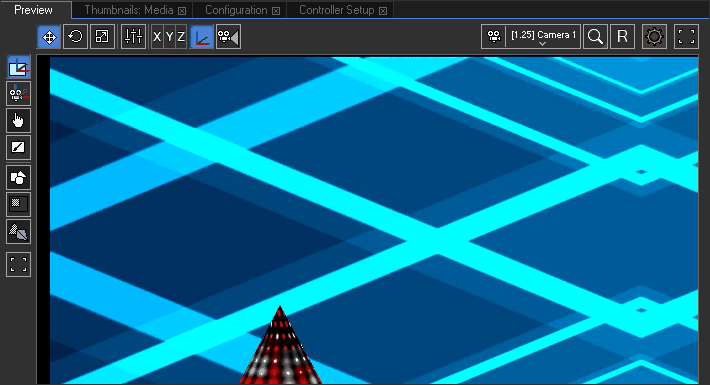 The Camera view shows what a Camera from a Site "sees", that is the so called render target or Composition pass. The render target is forwarded to the Output Pass where Output parameters like Softedge or Warp can change it. Hence the Output view shows the final result, the so called back buffer, that is also output through a Client's graphics card output. The chapter "Video Processing pipeline" explain the render passes in more detail. The Camera view shows what a Camera from a Site "sees", that is the so called render target or Composition pass. The render target is forwarded to the Output Pass where Output parameters like Softedge or Warp can change it. Hence the Output view shows the final result, the so called back buffer, that is also output through a Client's graphics card output. The chapter "Video Processing pipeline" explain the render passes in more detail.
The left image shows the left Camera from the scene depicted above.
By the way, renaming Cameras and Output Layers in the Device Tree also changes their names in the drop-down menu.
|
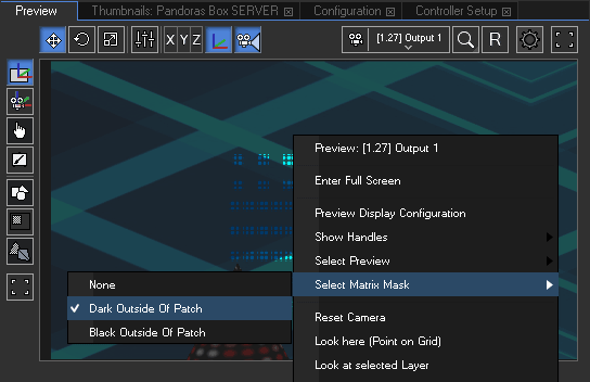
When working e.g. with LED walls that are controlled via Art-Net you can choose to preview the Art-Net output instead of the video (e.g. DVI) output. Whilst being in the Output (!) view right-click and select a matrix mask. To use the matrix feature you first need to create a patch in the Matrix Patcher and export it to your Pandoras Box project. Drag the new format ".pbx file" on any Output Layer. Now, you may choose to preview it. Right-click in the Preview > Select Matrix Mask > Dark or Black outside of Patch. Dark Outside of Patch dims the area not covered by the patch whilst the Black option does not display it at all. Choose None to see the entire area without the highlighted patch.
|
Multi-View
Since version 6 the Preview can be toggled to a Multi-View window. Per default you see one view port as usual, but now you can also choose to work with a split view with 2, 4 or 8 view ports in various arrays. |
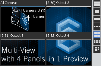 If you have loaded the "All Cameras" view before toggling to more view ports, the newly created ones will show "None"; in case you have loaded a Cameras (or Output) view, the newly created windows will automatically show other Camera (or Output) views if they are available. Of course you can change each view port individually using the drop-down menu. Please note that for the time being it is not allowed to view a Camera and the corresponding Output at the same time. Another restriction in this version is that one view can be loaded into one view port only. In other words, the "All Cameras" view or "Camera 1" can not be depicted twice. If you have loaded the "All Cameras" view before toggling to more view ports, the newly created ones will show "None"; in case you have loaded a Cameras (or Output) view, the newly created windows will automatically show other Camera (or Output) views if they are available. Of course you can change each view port individually using the drop-down menu. Please note that for the time being it is not allowed to view a Camera and the corresponding Output at the same time. Another restriction in this version is that one view can be loaded into one view port only. In other words, the "All Cameras" view or "Camera 1" can not be depicted twice.
Independent from the number of view ports, it is possible to maximize the Preview to full screen. This is especially of interest in case you warp several Outputs in the Manager using the Editable Mesh feature.
|
Previewing different Camera offsets
When changing the Preview to show the single cameras, each one would show its area according to the wireframes:
Camera 1
|
Camera 2
|
Camera 3
|
Camera 4
|
|
|
|
|
|
Previewing several Clients with equal Camera offsets
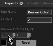
Having Sites that run separately from each other (with no X / Y Camera Offsets), the Sites outputs will overlay in the Preview by default. The output at top is from the Site that was added to the project at last. In the Inspector of Site 1 and Site 2 the Preview Offset may be changed. This way both Sites can be shown at the same time.
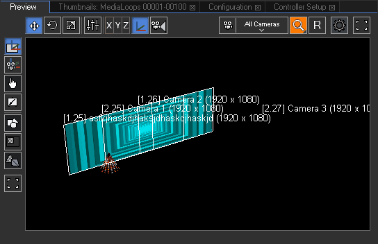 When changing to the All Cameras view, only Site 2 is visible, because it was added to the project at last, it overlays the Preview image of Site 1. When changing to the All Cameras view, only Site 2 is visible, because it was added to the project at last, it overlays the Preview image of Site 1.
In the Device Tree tab select Site 1 or 2 and turn over to the Inspector...
|
...and modify the Preview Offset of a Site by (1) entering X and Y values manually in the text fields or
(2) click in the little black box and move the mouse while holding the left mouse button clicked.
|
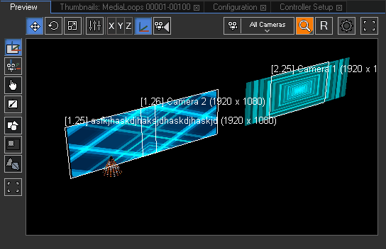 Image left: having different Preview Offset values applied to the Sites allows you to see both at the same time. Image left: having different Preview Offset values applied to the Sites allows you to see both at the same time.
The next chapter explains how to rotate, pan and zoom within the Preview tab.
|
