Loading...
This chapter explains the Mesh Editing Mode of the Preview which allows you to warp directly in Pandoras Box. For other topics regarding the Preview tab please see the introductory chapter. The next chapters cover theory and practice of warping. First, general warping questions are explained before a tutorial shows step-by-step how to warp in PB in a Manager-Client setup but also in stand-alone mode. The topic about the Multi-User tab explains the possibilities to work with several operators on one project, e.g. if one or more operators warp the screens whilst other ones take care of the timeline and content.

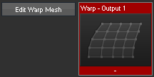
The fastest way to warp an Output is to select it in the Device Tree and press the "Edit Warp Mesh" button in the Device Control tab. This will automatically...:
1- create an Editable Mesh with the size of your output resolution and a 3x3 FFD grid, name it "Warp - Output no." under the project folder "Warp Meshes" and save it in the project path.
2- assign the Editable Mesh to the according Output.
3- toggle the Preview to the Mesh Editing mode.
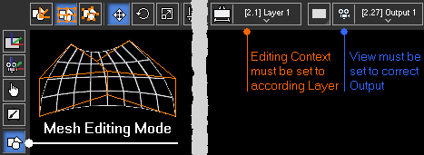
4- set the correct Editing Context and View which is then scaled out slightly in order to make the selection of FFD points easier.
If you click the "Edit Warp Mesh" button a second time, only step 3 and 4 are executed.


To do this manually...
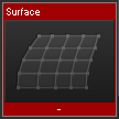
1- right-click in the Project tab and choose "Add Editable Mesh" and save it. Right-click the Mesh and choose "Rename" in case you prefer a more descriptive name. Check the size in the Sub Mesh Inspector. Note that the newly created Editable Mesh folder lists one Sub Mesh called "Surface" which is a planar 2D Mesh in fullscreen size with a 3x3 FFD grid.
2- assign the Editable Mesh or the contained Sub Mesh called "Surface" to your Output.
3- toggle the Preview to the Mesh Editing mode.
4- set the Editing Context (in the above image its highlighted in orange) and the View (highlighted in blue) to the according Output and scale it out slightly by scrolling with the middle mouse button.
Of course you can also assign the Editable Mesh to another Device e.g. a Video Layer.


A Mesh can include one or multiple Sub Meshes. If you assign the Main Mesh to a Layer, and there are multiple Sub Meshes all of them are assigned, i.e. the Layer texture is shared on all Sub Meshes. Of course, you can also assign only one Sub Mesh. To do so, you can open the Main Mesh folder and pick a Sub Mesh. If you would like to assign all Sub Meshes to individual Layers, right-click the Main Mesh and choose the command "Assign Sub Meshes to Devices Consecutively" after selecting the "starting" Layer.
If you would like to edit an imported object, simply right-click it in the Project tab and choose "Create Editable Mesh from Mesh".
The Object Inspector lets you change general settings like the wireframe color whilst the Sub Mesh Inspector includes options like the Segment count (known as Mesh points in the Warper), the Control Point count (aka FFD), Mesh size and segments, etc. If you are not familiar with the warping process, please also read the next chapter covering general warping questions.
 Note that in the Device Tree, the Layer that is picked as the Editing Context is marked with the Editing Context icon.
  In case you delete the Mesh from the Layer whilst the Editing Context is still referring to it, the Layer will be marked with a small red dot.
As soon as the Preview is set to the Mesh Editing Mode, the Mesh Segments (per default light gray) and FFD Control Points (per default orange) become visible. Above the Preview, there are many tools available.
Choose whether you want to select the entire Sub Mesh, FFD points, or Mesh / Vertex points. The shortcuts are the letters M, F and V. |
|
Choose whether you want to move, rotate or scale the selection. The shortcuts are the numbers 1, 2, 3 on the main keyboard. |
|
The Parameter Floater [Ctrl + P] shows the exact position in pixels. If you have selected more than one point, the "In Layer" position refers to the center of your selection. The "In Layer" position is the absolute position in regards to the Layer bounds whilst the "Local Change" is a relative input, i.e. it is added or subtracted from the absolute position and then reset to 0. |
|
If you work with an Editable Mesh that contains several Sub Meshes (Surfaces) you have the choice to select either one of the Sub Meshes or only the one you choose from the drop-down list. |
|
If you highlight one / several Constraints, a transformation is only executed along the chosen axis / axes. |
|
These buttons toggle the visibility of the Gizmo, the FFD grid and the Mesh Wireframe in the local Preview. The last button toggles the Mesh Wireframes for all Outputs. For more options, go to the Configuration tab > Preview Display or Client Display. |
|
This button can be found on the left site at the bottom and toggles your Preview tab to a fullscreen window. All tools are available within the Button Bar, that you can toggle with the shortcut [T]. Hence, the maximized Preview gives you the best overview when warping. |
To select one object or point, simple click on it or draw a selection box around it. To make a multi-selection you can either draw a greater selection box or, in case you select FFD or Vertex points, use the shortcut [Ctrl + an arrow key] after having selected the first point. The shortcut [Alt + an arrow key] moves the selection in terms of selecting the adjacent points.
You can transform the selection using the mouse, the keyboard or the dialog "Parameter Floater". With your mouse you can click on one of the selected points and then drag it horizontally or vertically. When holding the [Shift] key, the transformation will be applied along one axis only. For example if you move the mouse from left to right the X-axis is taken but as soon as the up-down movement is greater, the Y-axis is taken.
You can also work with the Gizmo, if it is visible. As soon as you position the mouse pointer on one handle of the Gizmo, it is highlighted in orange. Dragging the mouse results in a transformation along one axis. You can also work in another plane by highlighting one of the corners shown in magenta, cyan and yellow.
As an alternative to working in distinct axes, you can apply constraints. With an activated X Constraint (shortcut [X]) the Y and Z-axis are shown in gray and any transformation happens along the X-axis only.
Depending on your preference you can work either using the mouse or the keyboard, or both. At any time you can maximize the Preview tab in the Manager with this button ![]() and toggle the Button Bar with [T].
and toggle the Button Bar with [T].
|
Mouse |
Keyboard |
Choose the Edit Mode |
Sub Mesh FFD points, or Mesh / Vertex points. |
Alternatively, use the shortcuts: - [M] - [F] or - [V] |
Select points |
Select a single point by simply clicking on it. |
First, select all points with [Ctrl + A]. [Up/Down/Left/Right] key selects a single neighbor point. |
Choose a Transformation Mode |
Move Rotate Scale. |
Alternatively, use the shortcuts: - [1] - [2] - [3] |
Toggle the Axis Locks |
Alternatively, use the shortcuts [X], [Y] and / or [Z]. You can also hold the [Ctrl] key whilst dragging your selection. |
|
Edit the selection |
Now, simply click on one of the selected objects / points and drag it with the left mouse button up/down or left/right. Alternatively, you can open the Parameter Floater |
Move the selection with the shortcut [Shift + Up/Down/Left/Right arrow]. Alternatively, you can open the Parameter Floater with [Ctrl + P] and enter a number to an according number field. |
The next chapter covers general warping questions.