Loading...
This chapter explains the physical setup of a WD Recalibration scenario, what devices you need and what to pay attention to.
The Calibration Link is, in principle, a NET Link equipped with two Calibration Fiber input boards. Those boards allow measuring the light intensity levels of a 1mm fiber cable. The Recalibration process is based on these measurements. Hence, the quality of light transmission effects the quality of the process significantly.
The cable ends are mounted into the screen in a way that the fibers "look" straight at the projector to catch as much light as possible. The more offset the cable ends have, the more precise the calibration can be. At best, they are mounted into the corners.
A minimum number of four cables is required per projector. However, one can be shared by several projectors. So if you have e.g. a soft edge blend with two projectors, you can use six fiber cables (two in the overlap, and the other four near the corner of the screen).
Direct sunlight needs to be avoided.
By the very nature of the cables, they should be bent as little as possible.
Also, the fiber cables that form a group for one projector should be equally long.
The maximum length depends on the brightness of the projector. The longer the fiber cable is, the more light needs to hit the tip of the cable. As a rule of thumb, a 10m fiber cable require at least 100lx. If you have 20m cables then you need to have a minimum brightness of 200lx and so on.
The cable ends must be clean and cut as straight as possible. It is highly recommended to use a professional fiber cutter to do so, as other tools squeeze the fiber and reduce the transmission quality. Neither end of the actual glass fiber itself must stick out from the cable sheath!
Simply insert the cut off end into the Calibration Link's fiber input and move it slightly forward until it withstands, then tighten the screw-able input.
It is recommended that the projector pixels are in a best focus position for all fiber points.

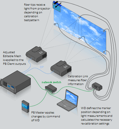
First of all, a PB Manager runs in stand-alone mode or is connected to other Clients. Widget Designer may run on the same or a separate hardware and is connected via network to the PB Manager and the Calibration Link. Fiber cables run from the Calibration Link to the screen and measures light from a projector that is connected to the PB Client.
1. The user starts the recalibration process by clicking a button in WD.
2. WD tells the PB Manager to load an Editable Canvas into the designated Client's output.
3. WD sends a sequence of black and white calibration patterns to the Canvas which are displayed on the Client's output (i.e. the projector).
4. According to their position, the fiber cables receive a certain light amount from each calibration pattern.
5. The Calibration Link measures the light intensities and transmits this information via network to WD.
6. WD calculates the position from the fiber tips (markers) relative to the projected image.
7. WD calculates the necessary recalibration settings and sends them to PB.
8. PB applies the adjustments to an Editable Mesh and loads it into the Client's output.
The whole process is completed within a few minutes.
The next chapter covers the software part and a step-by-step instruction how set this feature up in WD and PB.