Loading...
This chapter explains the software setup of WD and PB for a Recalibration scenario. If you want to know more about the physical setup, please refer to the previous chapter.
If you are already experienced with using the Recalibration, you can find a shortened step-by-step list at the bottom of this page for an overview of the necessary steps.
Please make sure that you are using WD version 6.1.0 and PB version 6.1.3 (or higher) for this feature and have .NET version 4.8 or higher installed.
Before you start the Recalibration setup, please have your Manager and Client setup up and running.
Additionally, please add an Editable Mesh for each output that is supposed to be included in the Recalibration, and warp it according to your screen. The Recalibration tool relies on this warp file to determine the adjusted warp parameters.
The more exact your initial warp is, the more exact the Recalibration is going to be afterwards.
Please note that the original Mesh file that you created yourself will at no point be modified by WD.
First of all, you need to retrieve the measured light intensities. For this, please create a Calibration Link input node and connect it to your Calibration Link hardware.
This node does not require to be connected to an output node.
When it is successfully connected, you should already see incoming values from your fibers. If you want to make sure that the physical placement of the fiber tips in the screen in relation to the projector is good, display a white image and check the received values in the Calibration Link dialog. The maximum intensity level is 1023. If you are not close to this value with a white pattern, please try optimizing your physical setup (i.e. for example the orientation of the fiber tips, see more at the bottom of this page).
Recalibration does also work with lower values, but you should aim for the best conditions possible.
Now make sure to establish a connection between WD and the PB Manager and then open the Projector Recalibration dialog from the Tools Menu.
When setting up the Recalibration for the first time, you need to select the desired PB outputs. Click on "Add New" to add one output to your setup.
The next step is to assign the available fiber inputs to each PB output.
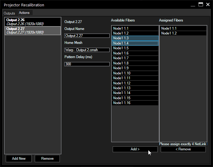
Select the output you want to edit to display its settings:

Here you can enter a different name to be displayed for your output than the automatically assigned one. It can be helpful to keep a better overview when several projectors are supposed to be recalibrated in one project.
This is also the name with which this output can be accessed via script commands later.
Enter here the exact name and folder path as it is displayed in the PB Project Tree of the already warped Editable Mesh, corresponding to the selected output, e.g. "Warps/Warp - Output 2.cmsh"
Enter here the time for the interval in which the calibration pattern changes. In certain cases it can be necessary to increase the interval, especially if the processing capacities of the WD or PB machine is limited or the connection between both is slow.
It is not recommended to enter a much smaller number than the default 300ms.
The left list contains all available input fibers from all Calibration Link nodes set up in the project. Select the four inputs corresponding to the output you are currently editing (multi-selection possible) and press "Add >" to assign them.
If you want to remove fibers from the assignment, select them and press "< Remove".
One fiber input can be assigned to multiple outputs, e.g. when you have an edge blend.
When you start the calibration, WD creates an Editable Canvas within Pandoras Box and uses this to display a sequence of specific calibration patterns to locate the fiber tips in the screen and calculate their position within the warped output. Those initial points are stored as the home location.
If the projector or screen is now moved slightly and the warping is off, the process of point location is repeated, and based on these light measurements the exact new pixel location can be determined. From the resulting position changes compared to the original configuration, WD calculates the necessary transformation that needs to be made for a new warp.
A second mesh file is created by WD (the original initial warp file is never altered), and the calculated changes are applied.
After you have your outputs set up, mesh files and fiber inputs assigned, you can start with the calibration process.
Select the Actions tab in the top-left corner of the dialog.
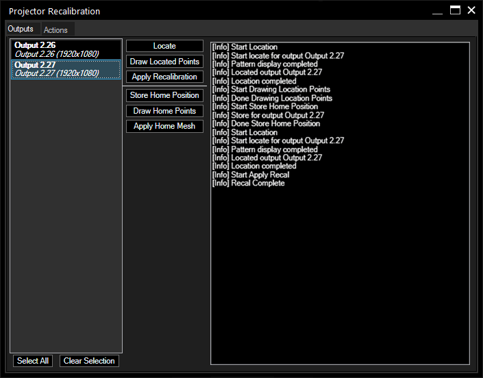
First of all, the home points need to be calibrated. Press "Locate" to initiate the calibration pattern. Then, press "Draw Located Points" to check the fiber positions and afterwards "Store Home Points" to save this as the home position.
This creates an Editable Canvas as well as an Editable Mesh for each output.
If your physical setup changes, e.g. the projector is being moved, you need to locate the new fiber positions first and then press "Apply Recalibration" for calculating and applying the new position adjustments.
Important: All actions reset the respective PB output, active values will be lost.

Press this button to start the fiber localization. If this is executed the first time for this output, it will create an Editable Canvas (e.g. "output_2_27") within the PB project.
The Canvas is loaded to the selected output and the calibration pattern sequence starts.
This action only stores the positions of the fiber tips internally, the actual recalibration has to be started manually afterwards.
If you want to check whether the fiber positions were recognized correctly, press this button to display crosshairs around the localized points in the Client output.
This button now takes the offset between the stored home points and the newly located points, and calculates the transformation of the mesh file needed to meet the new locations. This action is the actual recalibration.
By pressing this button, a copy of the original home mesh is created and modified. The original warp mesh remains as it is.
Press this button when you have located your home points for the very first time and before the setup changes. The positions of the fibers are stored internally.
It is crucial that the home positions are as exact as possible. To avoid error propagation between each calibration process, the recalibration always refers to the original home mesh and home positions.
If you have modified your original home mesh, please also store the home positions again.
This displays the positions of the stored home points and visualizes how much the setup has been altered compared to the initial state.
Press this button to copy the original Editable Mesh you have warped yourself in the beginning, and apply it to the output.
The log window displays valuable information [info] about the performed action. If a localization or any other action failed, you can see here why it did not work in an [error] or [warn] message.
It also displays when an action started and when it is finished.
In the above example you can see the messages relating to the following actions:
- Location
- Show Located Points
- Store Home Position
- Location (after setup was altered)
- Apply Recalibration
There are several scripting commands available for automating the recalibration process, so that you don't need to interact with the recalibration dialog. You can program a simple CustomScript button that needs to be pressed when the warp is off, or even establish a scheduled recalibration routine.
When you are working with scripts, please note:
- A command does not wait until a former action is completed.
- Calling multiple commands might cancel any action that is currently in progress (this depends on the command)
- Calling multiple commands will not queue them up, they will be performed at once. If you want to queue commands, please make use of WDWait with an appropriate wait time.
- All commands reset the Pandoras Box Output, i.e. as if you had initiated a Device Reset. Active values will be lost!
Find here a short step-by-step list for setting up a recalibration scenario:
1. Setup your PB environment with Manager and Clients, create and warp the respective Editable Mesh files in PB for each output you want to recalibrate.
2. In WD, create a Calibration Link input node and connect it with the respective device
3. Connect WD to the PB Manager
4. Open Tools > Projector Recalibration
5. Add Client outputs
6. Enter the warp mesh name
7. Assign fiber inputs to output
8. Go to the Actions Tab, select an output and localize the fiber tips
9. Check accuracy with "Draw Located Points" (optional)
10. "Store Home Position"
11. Alter physical setup, localize new fiber tip positions
12. Check accuracy with Draw Located Points (optional)
13. Apply Recalibration
14. Rejoice
To localize the calibration points, a series of black and white horizontal and vertical line patterns is projected. With pure logical combination Widget Designer then determines where each fiber tip is located.
This entire process of light based measurement and calibration requires that "white" and "black" can be clearly distinguished.
Possible reasons why a black pixel cannot be distinguished from a white one could be that black is too bright or white is too dark or even black equals white:
- too much (side) light on screen that raises the value for black
- broken projector lamp
- poor cable transmission quality
- broken Calibration Link board
- broken cables
- too long cables
- cables bent too much
- cable tips dusty, dirty, not cut properly
In the worst case, the projector moved so much that its light does not hit the fiber tips any more. So before starting the process, ensure that the projector covers all of its related fiber points as well as all of its dedicated screen-space and that the focus is alright.
If your value for white exceeds 1023, you may set the Calibration Link to coarse mode. It roughly doubles the value range. If you need to do that, open the Calibration Link and find a dip switch on the circuit board. If you need assistance, please contact Christie Pandoras Box support.