Loading...
The ProBel SWP 08 Input node lets you send and receive route states via the SWP 08 protocol using a TCP/IP connection. This way you can integrate Widget Designer in a VSM setup for example. Note that the implementation focuses on setting cross points, i.e. not all features of the SWP 08 protocol are implemented. Route commands can be either sent by using the graphical matrix depicted in the node or via node commands that can be executed by pressing a Custom Script button for example.
This node can be found under Nodes > Input > Devices > ProBel SWP 08

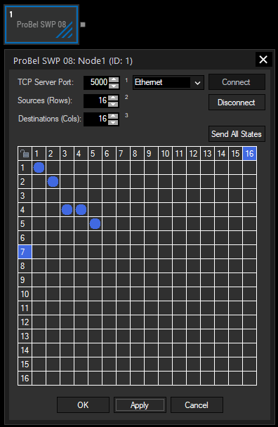
Enter the port to which your remote client(s) can connect to. The IP address can be defined by selecting a network adapter with the drop-down list to the right.
Once the port and NIC adapter are defined, press the "Connect" button to start the TCP server. Press "Disconnect" to stop it again.
Set up how many rows and columns should depict your sources and destinations for routing signals in the matrix. Note that Widget Designer starts counting from "1", not "0"; the maximum count is "192". Press "Apply" below the matrix to apply your changes to it.
This sends a message to all clients how the signals are routed according to the matrix.
The matrix lets you define cross points of source and destination signals. To route signals in this graphical user interface, first toggle the upper left lock symbol to its unlocked state. Then go down to the column from your source and to the right to the row of your destination and left-click in the according box. A blue dot depicts that cross point and the according route command is sent out to all connected clients.
You can route a source to multiple destinations (as shown above with source 4).
As described below, you can also route signals via node commands.
As long as you are connected, the node also receives route signals from the client(s) and shows the state in the matrix.
With Widget Designer version 6, all nodes support so called node commands. Node commands access functions (i.e methods) from a node and / or set a parameter (i.e. property).
Enter "Node", followed by the according ID and a dot and a list will pop up showing all available commands for the node. For instance, Node1.TintColor.SetRGB(125,0,255) colors the node in purple.
The node properties with a parameter ID (the small superscript number) can be edited via the command Node1.SetParam(ID,new Value) or WDNodeSetParam(NodeID,ParamID,Value).
In addition to the general commands, this node provides these specific function commands:
-Node1.Route(3,2)
This routes source 3 to destination 2. This is also represented in the matrix in the dialog of the node.
-Node1.SendAllStates
This sends a message to all clients with the information how all sources are routed according to the matrix in the dialog of the node.
The node generates the following output:
- Connected: True / False0,1
- Destination 1-192: State 0,1