Loading...
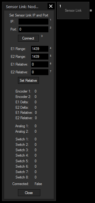
The Sensor Link input node provides the absolute, relative and delta values of the Sensor Link device - the encoder inputs, the analog 0-10V inputs and the switch states 1 to 8.
This node can be found under Nodes > Input > Devices > Sensor Link

Please enter the Sensor Link's IP as well as Port number and press Connect.
E1 Range:
Enter the encoder's amount of steps. If the encoder provides 1440 steps, enter 1439 because the counting starts with zero.
Please note that the encoder's range has to be entered in the SensorLink Configuration Tool, too.
E2 Range:
Enter the encoder's amount of steps. If the encoder provides 1440 steps, enter 1439 because the counting starts with zero.
Please note that the encoder's range has to be entered in the SensorLink Configuration Tool, too.
E1 Relative:
Enter zero to reset the relative step count for the current encoder position or enter an offset value.
E2 Relative:
Enter zero to reset the relative step count for the current encoder position or enter an offset value.
With Widget Designer version 6, all nodes support so called node commands. Node commands access functions (i.e methods) from a node and / or set a parameter (i.e. property).
Enter "Node", followed by the according ID and a dot and a list will pop up showing all available commands for the node. For instance, Node1.TintColor.SetRGB(125,0,255) colors the node in purple.
In addition, the node properties with a parameter ID (the small superscript number) can be edited via the command Node1.SetParam(ID,new Value) or WDNodeSetParam(NodeID,ParamID,Value).
The node generates the following output:
- E1
- E2
- Analog 1
- Analog 2
- Switch 1
- Switch 2
- Switch 3
- Switch 4
- Switch 5
- Switch 6
- Switch 7
- Switch 8
- E1 Delta
- E2 Delta
- E1 Relative
- E2 Relative
- Link Connection State