Loading...
This topic explains how to set up the frame lock option for FrameSync and frame and pixel line accurate synchronization. Please refer to the main chapter if you are interested in other NVIDIA settings, for example settings for resolution, multiple displays, and the driver.
As with all display settings, we recommend to close Pandoras Box before applying any changes.
The frame lock option is for NVIDIA cards with a sync board, for example the P4000 or RTX A4000, and is available for Server hardware. These graphics cards have the possibility to synchronize to an external gen lock signal or to the sync signal generated by the sync board itself.
These are possible and recommended scenarios how to use the sync board:
 In case you have one system only and want to be sure, that all outputs are synced, please use the Mosaic mode as described in the previous chapter. |
- One or multiple system(s) listening to an external gen lock signal generated by another third-party device
In this case, connect the sync signal via the BNC connector on the sync board to each system and set up each system to receive an external sync signal.
In any case, the sync signal must fit to the frame rate that is set up in the graphics card, otherwise the timings can not be synced.
Then the below described driver settings are necessary to set up the graphics card. It will then clock to the incoming signal. This procedure might take up to 10 minutes as the card's clock needs to shift step by step towards the external clock.
For your information, if you need frame locked inputs, you need to feed the sync signal to the device that produced the live feeds and make sure that the live inputs are fed frame locked into Pandoras Box.
After setting up a timing leader, the sync card can output the sync signal which can then be used in other systems.
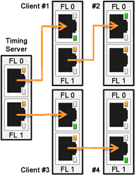
The leader provides an external sync signal via the RJ-45 plug on its sync board. Connect the board's output with an ethernet cable to the input of the next Server, which is then the client. You may daisy-chain the sync signal to all clients as depicted above.
Open the NVIDIA Control Panel as described in the first chapter and then the menu "Synchronize displays".
If you have multiple displays attached to one graphics card, they can be set up as separate outputs or can be combined using Mosaic mode. In both cases, choose in the "Synchronize displays" menu that the timing server is "On this system". Without the mosaic mode, select in the second section that all displays should be locked. With the Mosaic mode, you cannot choose other displays as they are already combined.
This is how the menu "View system topology" looks before and after setting up the timing leader, first for the setup with two separate displays, and below the setup using Mosaic mode.
After setting up a timing client, the sync card locks to the sync signal received from another system.
Open the NVIDIA Control Panel as described in the first chapter and then the menu "Synchronize displays". Choose that the timing server is "On another system" and activate your outputs in the second section.
This is how the menu "View system topology" looks before and after setting up the timing leader.
After setting up a gen lock, the sync card locks to the sync signal received from another device. Please check the Sync card chapter which timing sources are supported.
Open the NVIDIA Control Panel as described in the first chapter and then the menu "Synchronize displays". Choose that the timing server is "On this system" and activate your outputs in the second section. Then click the button "Edit Settings" to set the properties of the frame synchronization pulses generated by the timing server.
- choose the setting "An external house sync signal" as the basis for the synchronization pulses
- make sure that the sync frequency matches with the frame rate
- only if needed, change the drop-down list for the sync signal detection and tick the check box whether the "signal is interlaced"
- choose how the sync pulses from the frame start signal should be triggered: leading -, falling -or both edges
- in most cases the outgoing sync interval is 0
- set the correct Sync delay, then "Apply" the settings to verify their correctness
- the sync delay depends on your setup and the current graphics card clock. It is likely you will have to try out different delays. As experienced, it is mostly 300-500µs, you may start with 300µs and increase in 50µs steps if it was not correct. Mind that it takes the system up to 10 minutes to reach the set clock.
Last step: You may check the "View system topology" menu whether all settings are correct:
- the external sync signal should be present and in use
- the frame lock sync pulse should be present
- the first display should be listed with "Output (1 of 2)", the second with "Output (2 of 2)"
- the first output's display state should be "Server" and its timing depends on the external house sync signal
- the second output's display state should be "Client" and its timing depends on the internal frame lock sync pulses