General 3D Modeling Terms |


|
General 3D Modeling Terms |
|
General 3D Modeling Terms |
|
General 3D Modeling Terms |
|
Loading...
This chapter covers the common 3D modeling term definitions:
- coordinate system
- generic units
- Vertices, Pivot Point, Edges and Faces
- UV texture mapping
- mesh versus FFD
Please make yourself familiar with these terms. They will be used in the following chapters when the Warper interface and workflow is being explained. As well, the explanations might help you when communicating with 3D artists who prepare 3D models for you or when getting in touch with one of the third party applications yourself.
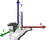
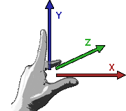
Each 2D and 3D world needs a coordinate system which defines the position and orientation of each object. There are two possible systems: the right-handed and left-handed system. In both systems the positive X and Y direction are the same and show to the right and upper side (as seen in the picture below). The Z axis makes the difference, it shows either to the back or to the front.
Pandoras Box and the Warper are based on the left-handed system. If you import an object from an application that is based on another orientation make sure to adapt it.
 |
 |
The origin of the 3D space (X,Y,Z) = (0,0,0) is situated in the exact middle of the screen when starting Pandoras Box and the Warper with default settings. The origin is the reference point for every object. The camera has a position of (0,0,-25) and a FOV (field of view = opening angle) of 35,489 degree (or 56,251 mm).
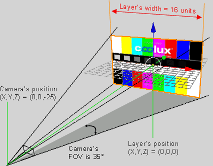
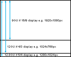 Many 3D modeling programs can save an object with so called generic units (GU), e.g. a cube may have a height/width/depth of 8 GUs, rather than being measured in metric or pixel units. The advantage is that GUs adapt to the current screen, they "generate" a relative size and must not be scaled when the resolution changes. Per default a screen width is exactly 16 GUs, the height is calculated by the aspect ratio. Hence, a 4:3 display is 16 GUs wide and 12 GUs high, whereas a 16:9 display has the same width but a height of 9 GUs. The Warper and Pandoras Box are based on generic units since version 5. The coordinates (X,Y) = (0,0) are situated in the middle of the display. If a layer or object moves 8 units to the right its center will be exactly on the right edge of the screen. |
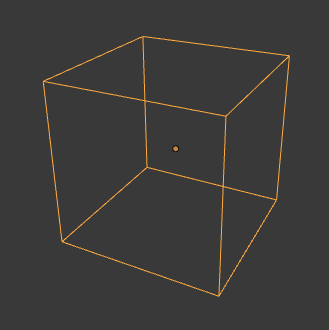
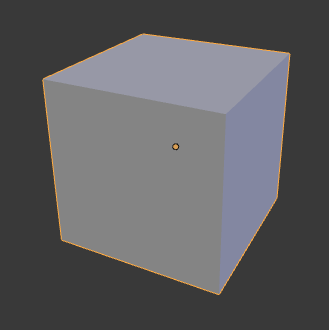
The default mesh in the Warper consists of vertices as well, the more mesh segments you set up, the more vertices are generated by the Warper. In most 3D modeling programs there is a so called pivot point. In the left image it is depicted as a round orange point. The pivot starting point is the center of a transformation like rotation and scaling. If the cube is scaled, all vertices still would have the same distance to the pivot point. For more examples, please see the topics Scale Pivot and Rotation Pivot in Pandoras Box. |
|
The next hierarchy is then called "polygon" whereas one or more face(s) form one polygon. The outlines from a polygon are the edges.
No matter how your 3D modeling program works, either faces or polygons can be applied with a texture. |
  The UV mapping transforms a 2D source image (in our case an image or video) into an image buffer called a texture. In contrast to "X", "Y" and "Z", which are the coordinates for the rendered 3D object, "U" and "V" are the coordinates of the texture. The UV map stores for each X,Y,Z- coordinate a defined U,V-coordinate. This creates the effect of painting the image onto the surface of the 3D object, or in other words, how to wrap or stretch the image around the object. As explained below there are different ways how to do that, hence the chosen UV map is stored as a property of the 3D model. If a 3D model has no UV map, neither the Warper nor Pandoras Box can paint a texture on it which leads to the fact that the object is invisible and cannot be displayed. The Warper has tools that can influence the UV Map, e.g. scale or move it. When not importing 3D models from third party programs but working with meshes in the Warper you can define how to apply a texture on it. A texture can cover more than one mesh as well. This is described in the chapter "Edit Menu". |
|
 - planar - cubic or box - cylindrical and - spherical mapping. Planar mapping can be referred to an image projection from one side onto an object. |
|
 |
|
 |
|
 For proper spherical mapping textures with an aspect ratio of 2:1 apply best to a spherical object. |
|
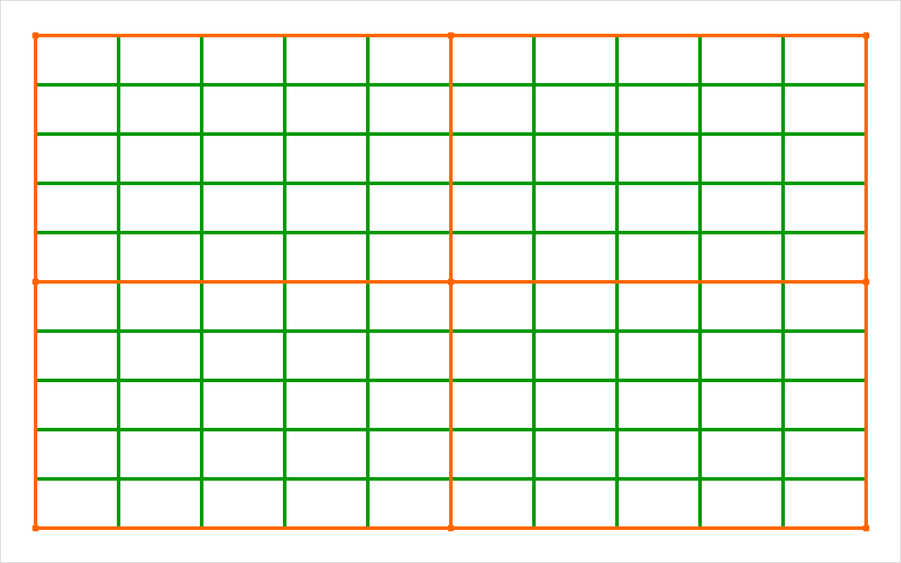
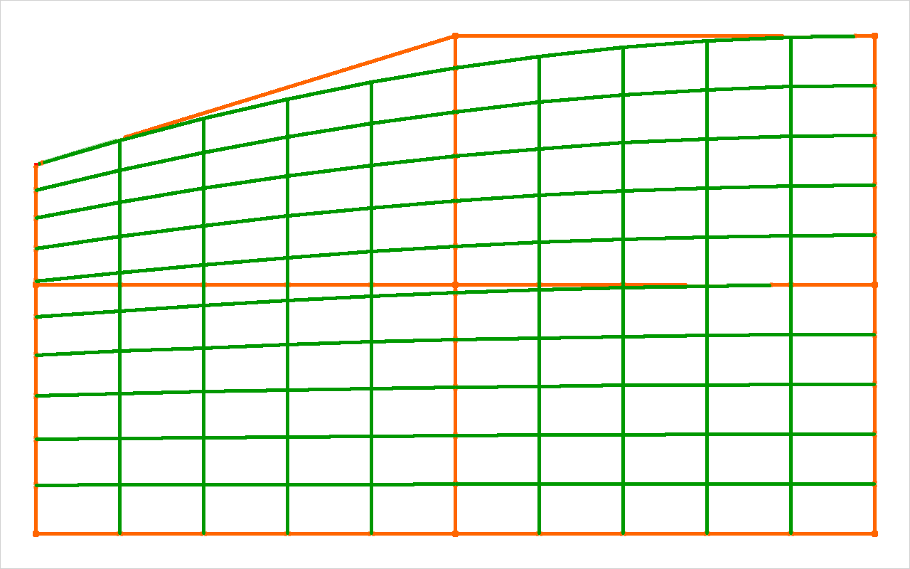
This paragraph describes the difference between a mesh point and an FFD point, thus it is covering a fundamental function of the Warper.
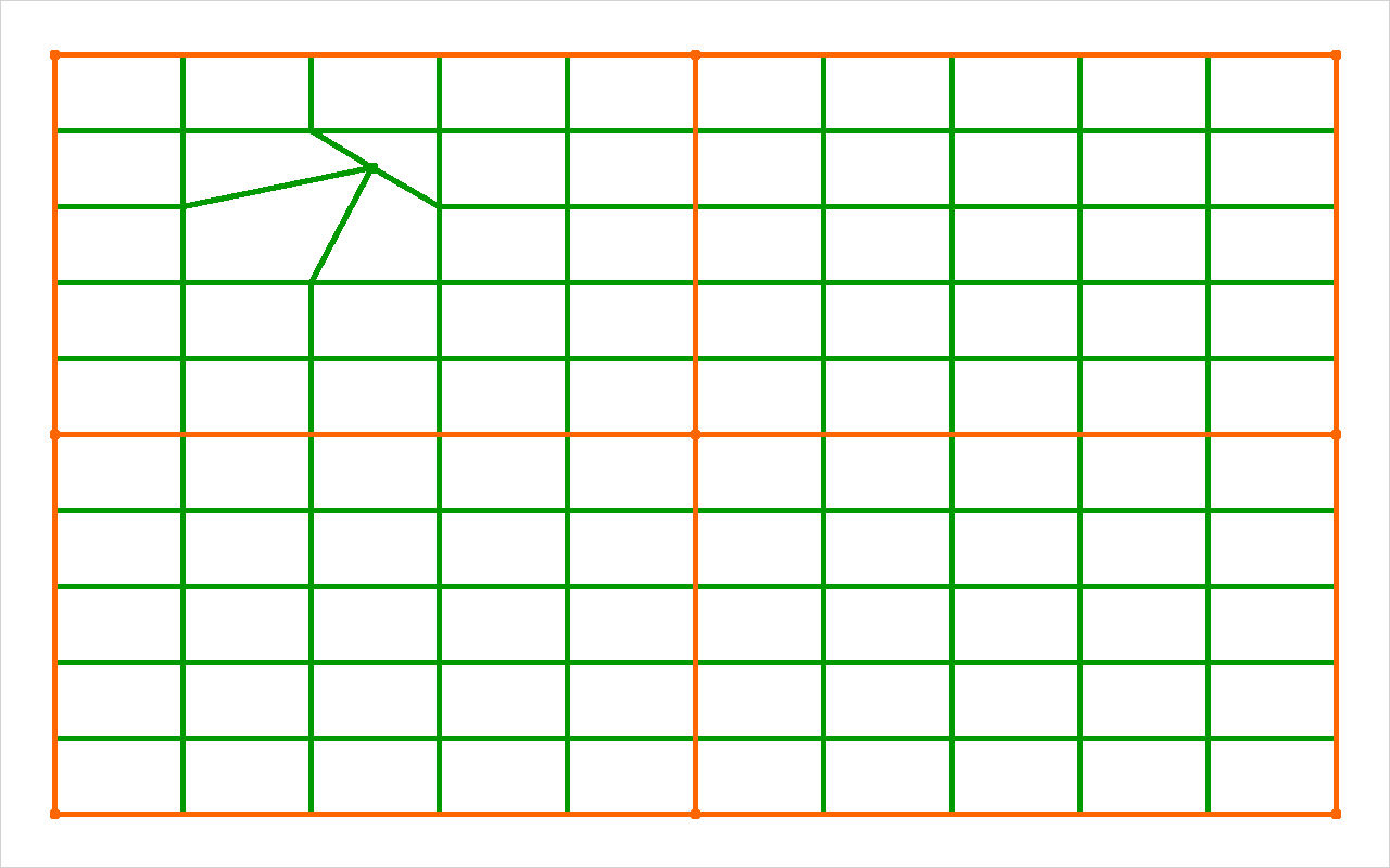
The pictures below show a 2D plane with a green-colored 10x10 mesh and orange-colored 3x3 FFD.
See here the differences between moving a FFD control point and moving a mesh point. Please note that the FFD is only a helping tool to set up the mesh, you won´t see the FFD in the exported object.
|
|
|
For more information about how to use the Warper please refer to the following pages:
User Interface,
Warping Guide,
Keyboard Shortcuts
If you are interested in other 3D modeling programs, please refer to the topic covering third party applications.
 Every 3D model and geometric shape consists of corners and intersections. These special points are saved as so called "vertices" (singular: "vertex"). In a 3D space a vertex must consist of three coordinates, X,Y and Z to definitely mark the position of a corner. A cube, for example must be defined by a minimum of 8 vertices. In the example, these are the small blue points.