Loading...
 |
|
 |
|
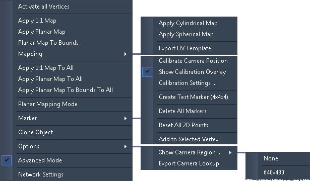
If you toggled some vertices/faces of the mesh with the shortcut [D] to be invisible, you can activate all hidden vertices again using this menu entry.
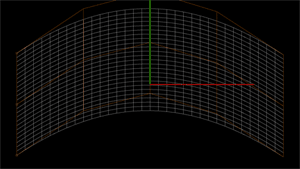
The following commands change the UV texture map for generated planes and objects. If you are not familiar with UV mapping, the chapter "General 3D modeling terms" includes a short section covering it and can get you started with that important 3D modelling technique. The Mesh tab allows to offset and zoom a previously applied UV map.
 |
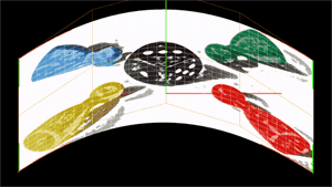 In the Texture tab you may find the button "Load Texture...".It applies a texture 1:1 like, that is, the texture is scaled and deformed to fit exactly into the corners of the mesh. The command "Apply 1:1 Map" always brings you back to that state. It applies a texture to the currently selected mesh or object. |
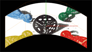 This command applies the texture to the selected mesh in a way that it is first scaled to the current fullscreen resolution and then applied to the mesh without being influenced by its scaling, position or deformation. It stays planar. One could imagine that the fullscreen texture is projected and burned into the mesh. If you now deform the mesh further, the deformation applies to the texture as well. If this is not required you may apply a planar map again. |
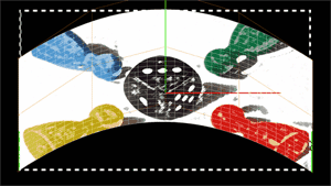 This command applies the texture to the selected mesh in a way that it is first positioned and scaled to the bounds of the mesh. The size of the mesh is indicated in the left image by the white dashed line. Then the texture is applied to the mesh without being influenced by its deformation. It stays planar. One could imagine that the resized texture is projected and burned into the mesh. If you now deform the mesh further, the deformation applies to the texture as well. If this is not required you may apply a planar map again. |
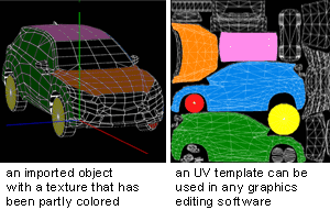
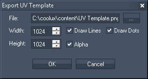 The command "Export UV Template" generates a template that can be used for creating content that should be mapped on the object. The feature unfolds an object, the result is a 2D image that can be colored in and later used as a texture on the object. For modifying the UV template you may use any graphics editing software of your choice as the UV template is saved as a PNG file. |
 The ideal width and height of the UV template depend on the object. The higher the resolution the more details can be shown but the more performance is drawn. "Draw Lines" will show the edges of the faces. In the Warper you can not see faces, but the larger polygons when activating the Wireframe mode in the Texture tab. "Draw Dots" referes to the vertices themself which are shown as red crosses when activating them in the General tab. If ticking the "Alpha" check box there will a transparent background instead of a black background. Vertices and edges are always white. |
A UV map can cover several meshes and objects at the same time, that is, it applies to one mesh only partly. This is for example of interest when...
1) you would like to show one layer on two separated screens
2) you have a complex screen that could be divided into several regions in order to make the warping process easier and faster. Imagine, that you want to project on a facade. Everything should be covered by the same picture. The facade probably consists of areas that are differently complex. Maybe there are quite plane areas and others, that need some more warping, e.g round pillars or stucco decoration. On these areas you can place meshes with a finer mesh grid and more FFD points. On the easier parts you can place more rough meshes. The alternative would be, that everything is covered by a mesh that has everywhere the same fine grid resolution. This would mean that you spend a lot of time on the easier parts too, as you have to work with unnecessary mesh points.
For both applications the following mapping commands can be helpful. For understanding the meaning and potential of planar mapping it is recommended to build some examples and try it out practically.
|
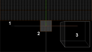
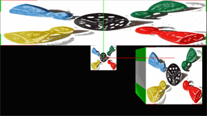 In the Texture tab you may find the button "Load Texture...".It applies a texture 1:1 like, that is, the texture is scaled and deformed to fit exactly onto each mesh and object that exists in your project. You do not need to select a mesh or object first. The command "Apply 1:1 Map To All" always brings you back to that state. As seen in the cube object, the texture is applied in a planar way, the front face shows the image, the side face stretches the left pixel line. The same is happening on the right,top and bottom side. |
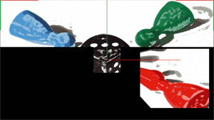 This command applies the texture to all meshes and objects in a way that it is first scaled to the current fullscreen resolution and then applied to them without being influenced by their scaling, position or deformation. It stays planar. One could imagine that the fullscreen texture is projected and burned into the meshes. If you now deform the meshes further, the deformation applies to the part of the texture as well. If this is not required you may apply a planar map again. |
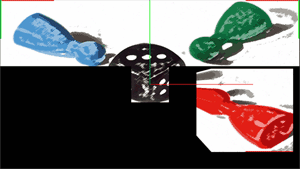 This command applies the texture to all meshes and objects in a way that it is first positioned and scaled to the bounds of the meshes. This can be best seen in the above described section "Planar Map To Bounds" where the size is indicated by a white dashed line. Then the texture is applied to the meshes without being influenced by their deformation. It stays planar. |
An activated Planar Mapping Mode applies the chosen texture constantly onto all meshes and objects in the project. The texture is not influenced by their scaling, position or deformation, it stays planar until the mode is deactivated again.
This is useful for positioning and scaling meshes before the Warping process as described above.
Please find a general description of markers in the topic describing the Marker tab.
SHOW CALIBRATION OVERLAY
An activated Calibration Overlay is the default state. If you deactivate this option, the object will always be rendered in the Wireframe mode (i.e. the texture will be hidden) as soon as you enter the Calibration mode when working with Markers. This is useful when you want to position a marker without being distracted by the texture.
CALIBRATION SETTINGS
A new dialog opens where you can influence the calculation that is called to estimate the camera position after setting up markers. The calculation is based on an algorithm that runs a defined number of times until it finds a position for which the two instances of all markers match each other, allowing a certain accuracy. If the result does not meet your expectations you can set up, that the algorithm should run more often, e.g. to reach the expected accuracy. Whether a more accurate (less than 0.00010) calculation or a more tolerant one gives better results, depends on your setup.
CREATE TEST MARKER
This command creates four markers that can be used to estimate a camera position automatically as described in the Marker tab.
DELETE ALL MARKERS
Choose this command to delete all markers.
RESET ALL 2D POINTS
After adding a marker to the project, a 3D point and a 2D point are generated. You may relocate the second instance, the 2D point, onto the real object (in the projected image). Choose "Reset All 2D Points" to discard this reposition and bring back the second instance. According to the current view, the 3D point and the 2D point share the same position again.
ADD TO SELECTED VERTEX
First, select a vertex from your 3D object, then choose this command in order to attach a marker to it. Instead of this workflow you may as well add a marker using the Marker tab.
The command "Clone Object" allows to make a copy from the currently selected 3D object or 2D plane. If you are in the FFD mode, please make sure that all FFDs are selected. If you are in the Object mode, just select the object or plane that should be copied. Now, go into the Move mode and drag the object whilst holding down the right mouse key.
In the Options menu you may find settings of interest when working with a camera tracking. A problem that you might encounter is, that the image seen by the camera is distorted due to a non-orthogonal camera position or due to lens deformation, the so called cushion effect. Same as with projectors, the (input) image needs to be keystoned or even warped. This is especially needed if the projector(s) is (are) not positioned on the same axis and output the image in a different angle.
The goal is, that the input coordinate of a tracked point can be translated into an output coordinate.
First, open the Warper on the computer where your Camera is attached to. On the default mesh, apply the video input image as a texture. You may do this is in the Texture tab. Now, open the Options menu and choose in the command "Show Camera Region" your camera resolution. Relative to your local screen resolution, a blue rectangle marks the camera size. Depending on the camera position and how it records the scene you need to deform the mesh in order to have a straightened tracked region as if the camera would look straight onto it without lens deformation, see the example depicted left. As a last step in the Warper, choose "Export Camera Lookup" and the directory whereto the *.dat file should be saved.
With the lookup table, the tracked input coordinates can be translated into valuable output coordinates (for a layer). |
Now, the lookup table can be used in the Widget Designer for example. In the Camera Point Tracker tool you may find the check box "Use Lookup". Click the [...] button to choose the directory from the saved *.dat file. Press the "Apply" button.
If a person now walks along the top edge for example, the tracked camera point will report a movement in one axis only, e.g. from (X,Y) = (0,0) to (640,0). Without the lookup table the same movement would have resulted in an X position change and Y position change, e.g. (200,20) to (530,60). It would have been impossible to prepare a Widget Designer project without knowing the exact camera position and how the input image looks like. With the lookup table you may straighten the image according to the camera position and use prepared Region nodes or Custom Script Buttons that are positioned in certain areas on your page. For example you can take a draft image from the scene and use it as a background image for your Widget Designer page. With the lookup table you can as well use the Camera Input node and route the X,Y Pos directly into a Range node and PB Device Output node without further calculation.
The Warper application starts per default in a basic mode, that is, certain menus, commands and tabs are hidden. Activate the advanced mode to have access to all functions of the Warper.
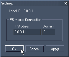
The next time you export a mesh or mask, it will be added to your Pandoras Box project automatically.