Loading...

The "Camera / View" tab is hidden in the basic mode. To activate the advanced mode, open the "Edit" menu and choose "Advanced Mode". This is only available in the Warper 3D edition.
The tab enables you to adjust the position, orientation and lens settings of a camera in the Warper. This is needed when you do 3D Warping as described in the introductory chapter. A camera can be added and selected in the camera selection field at the top right of the Toolbox. Choosing a different camera will change the currently seen settings in this tab.
Please read the last chapter to learn how to transfer these settings to a camera in a Pandoras Box Manager system. The next chapter covers a marker based camera calibration.
Position, Look At, RollThe six parameters for the X, Y, Z Position from the camera and its "Look At" target plus the roll parameter define where the camera is positioned, where it is looking and how it is orientated. As said in the introductory chapter where 3D Warping is compared with 2D Warping, you need to adjust the camera's and the object's position and orientation as well as the lens setting. Regarding the position and orientation, there are two possible ways to do so: manual measurement or marker-based calibration. |
FOV, LensThe parameters FOV and Lens express the same setting: the opening angle. When you enter the FOV, the Lens parameter is automatically calculated and vice versa. There are two ways to find out the opening angle: manual measurement or iteration. Alternatively you can simply try out and approximate what the lens factor is. If you have a lens with a fixed zoom, use this lens factor and try out whether a slightly higher or lower number gives better results. (Even fixed zoom lenses, can slightly change due to mechanical vibrations.) If the lens has a variable zoom, start with the smallest lens factor and increase it slowly. It is clearly visible in the projected image whether you are approaching the correct factor or not. |
AspectThe Aspect parameter expresses whether the cameras aspect mode is the same one as the output's aspect mode. |
Near Plane, Far PlaneNear and Far plane define what part of the cameras cone is rendered. If an object lies outside of the range, it is not seen and rendered by the camera. In 99.9% of all cases the default values give good results and should be not be changed. |
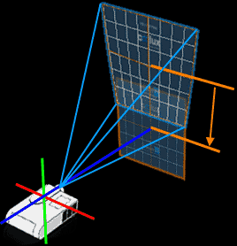
Lens Shift In the case that the lens shift cannot be adjusted in the projector, use the lens shift parameters in the Warper. In practice you can measure the lens' center to the floor and mark it on your screen depending on the projectors angle, or you can use a laser. At the end you should be able to know where the unshifted image center should be. Then adjust the lens shift so that the center of a default mesh is at the same height and width as the marked lens center. That could mean of course that parts of the mesh are outside of the projected image. This will be corrected after adjusting the position and orientation of the camera. |
The Reset button resets all parameters. Please note, that there is no undo function!
- Zoom: Scrolling with the mouse wheel influences the camera's Z position
- Rotation: Moving the mouse whilst holding the [Alt] key and the middle mouse button influences the camera's X and Y position. As all other parameters are not influenced this has an effect as if the camera rotates around a fixed point.
- Pan: Moving the mouse whilst holding the middle mouse button influences the camera's X and Y position and the "Look At" position at the same time.
For a finer adjustment, activate the option "Mouse Fine Mode" in the Keyboard / Mouse tab.
At the same time you may set up these and other settings, e.g. lens settings, with the numeric boxes in the tab. You may enter a number directly or increase / decrease it. For this you can either use the up / down buttons next to each field, or click once into the numeric box and scroll using the mouse. The in-, decreasing adjustment can be made more or less precise with the radio buttons: Coarse Mode, Fine Mode and Finest Mode.