Loading...

The "Marker" tab is hidden in the basic mode. To activate the advanced mode, open the "Edit" menu and choose "Advanced Mode". This is only available in the Warper 3D edition.
The tab enables you to add and position so called markers. As well view settings concerning the marker representation can be found here. There are more commands under Edit > Marker.
Please read the previous chapters to learn what the Warper camera's parameters are and how to transfer them to a camera in Pandoras Box.
Markers enable an automatic calibration of a camera's position and orientation (but not its lens settings!). A minimum of 4 markers is needed to adjust a camera in a 3D environment. The marker-based calibration is an alternative to manual measurement (of the projector's and screen's XYZ position) and data transfer to the parameters in the Camera tab. Both ways are attempts for a virtual 3D representation of the real 3D setup. Please keep in mind that this is not always necessary. Especially when working with only one camera or without 3D objects you can realize warping as well by straightening the projected image with a 2D mesh. This workflow is described in more detail in the introductory chapter.

Before you start warping, you might want to setup an additional screen to have an better view of the Warper interface (as the projected interface is obviously distorted). You could either connect a second display and set the display driver to clone/duplicate the screen. Or you could connect another computer via VNC to the computer that is connected to the projector and that runs the Warper.
Import the 3D model from the screen / object you are projecting on. It must match the real screen / object as accurately as possible. However, if changes were applied to the real object after the virtual model has been created or if it simply does not fit, you can adjust the model by moving its vertices. If you are projecting on a two-dimensional screen you can create the object in form of a mesh in the Warper directly. Choose File > New and set a size according to the real screen's dimensions.
Open the "Edit" menu and activate the "Advanced Mode". Adjust the object size if needed (as described in the Tools Bar) and the view in the Warper (as described in the previous chapter) so that the interface looks very roughly like your view onto the object.
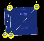
Now you can start adding markers. A minimum of 4 non-planar markers is needed when working with a 3D object. "Non-planar" means that one point must not lie on the plane that is defined through the other 3 points. When working with a 2D object, on the other hand, a minimum a 4 co-planar markers is needed. "Co-planar" means that all 4 points must share the same plane. In general the best results are achieved when placing the markers "far away" from each other.
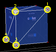
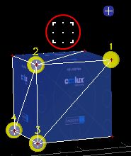
1. step: adding markers a) Click on the "Add" button. The mouse cursor becomes a thick plus (+) icon when the mouse is within an object. Click onto a vertex to add the marker there. If you have many vertices and the marker did not snap to the right one, you can select the right vertex and click the button "Snap Sel Vertex" b) Select a vertex by clicking on it directly or by selecting it through a selection rectangle. Now, choose "Edit > Marker > Add to selected vertex" to add the marker there. You may modify the view, rotate or zoom, at any time. This is useful when working with an object with many vertices, as it can be tricky to pick a certain one. If you are done with the fourth marker, adjust the view so that you can see all markers again; if you would like to relocate all 2D Points to the position of the 3D points, choose "Edit > Markers > Reset all 2D Points" Now we have placed the markers, or rather the yellow 3D points of them. The next step is to position the blue 2D points. |
  Underneath the check box there are two radio buttons "2D" and "3D". Again there are multiple ways how you can influence the position of the 2D points. Please note that the camera view must not be altered from now on. b) Use the shortcuts [Shift+ up/down/left/right arrow key] to move the selected marker. To select a marker you may either click on the according yellow 3D point (but do not move the mouse!) or select another marker by changing the drop-down list and them cli. c) Use the number fields "Screen X" and "Screen Y", especially for fine-tuning. If you have difficulties locating the cursor (and the attached 2D point) it could be helpful to activate the "Show Crosshair" option in the General tab. At the end all four 2D points are moved to the according spot from the real screen object. In other words, the 2D points have formed a specification for the camera position that needs to be found in the next step. |
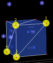
3. step: the Warper calculates a new camera position Now an algorithm runs over and over and returns the best possible position for the camera. From this position the camera sees the object just like the real projector "sees" the real screen. As a result the virtual object with its "glued" yellow 3D points is depicted in the camera view in such a way that the blue 2D points share the same position again. If the result does not meet your expectations, please check the following options. |
- Are the lens settings set up in the correct way?
Please select the Camera/ View tab. If you have a projector with a fixed lens shift or if you cannot shift it to 0,0 for any reasons, enter the lens shift (X and Y) in the according fields and run the calibration again by clicking "Update Cal". The algorithm now considers this offset in the calibration.
Please check as well whether the FOV accords with the lens factor of the projector lens. How to measure it is explained in the section "FOV / Lens". You do not necessarily need to click the "Update Cal" button. With an active Calibration Mode, you can tick the check box "FOV Re-Cal" and now, the calculation is done each time when a new FOV is entered. This way you can find the correct settings in just a couple of seconds.
- Is the 3D model correct?
Obviously the calculation depends on the accuracy of the 3D model. If changes need to done to the model you can select a vertex and move it to the correct position. You may transform a selection of multiple points as well.
- Are the 2D points positioned correctly?
Try to find a better position for the 2D points (using the mouse or the number fields as described above). You do not necessarily need to click the "Update Cal" button each time. With an active Calibration Mode, you can tick the check box "Live Re-Cal" and now, the calculation is done each time when a new position is entered. This way you can find the correct position in a very short time. Due to the cushion effect from the lens it's quite possible that the 2D points must be placed slightly outside the object.
- Have you tried adding more markers?
As said above the minimum marker number is 4. Adding more markers can give better results. When working with a 3D model, place additional markers outside of planes defined by three other markers as then a plane is overdetermined.
- Does the projector lens have a strong cushion effect?
If the projector distorts the lines due to a strong cushion effect you may apply a mesh to the output layer that evens it out. A good way to generate the needed mesh is to first apply all settings to the PB camera that were found with the current project. Then you may open a new project with a default mesh and use the Live Warping feature.
- Have you tried other options for the algorithm?
Under "Edit > Marker > Calibration Settings" there are options that adjust the algorithm.
yellow color field |
click into the field to open a dialog where you can pick another color for the 3D points and their ID |
drop-down menu |
allows to select another marker to adjust the according position of the 3D (parameters X Y Z) and 2D point (parameters Screen X and Y) as well as the 3D point's color and size (parameter radius) |
button Add |
turns the mouse cursor to a thick plus (+) icon and generates a marker when clicked |
button Del |
deletes the marker chosen in the drop-down menu; this command cannot be undone! |
check box Snap |
when a marker is added to the object with an activated Snap function, it will snap to the nearest vertex |
button Delete All |
deletes all markers; this command cannot be undone! |
button Snap Sel Vertex |
snaps the selected marker (via the drop-down menu) to the vertex that has been selected |
button Snap Next Vertex |
snaps the selected marker (via the drop-down menu) to the nearest vertex; if a marker is already located on a vertex it will not change its position |
number fields X, Y, Z |
position of the 3D point of a marker |
number fields Screen X, Screen Y |
position of the 2D point of a marker |
number field Radius |
size of the 3D point (in generic units) |
check box Calibration Mode |
activates the Calibration Mode (and its overlay), i.e. the mouse cursor changes to a cubic-like icon that allows to drag the blue 2D points; only with an activated Calibration Mode it is possible to activate the FOV Re-Cal and Live Re-Cal |
radio buttons 2D / 3D |
must be chosen before the calibration is started; |
check box FOV Re-Cal |
enables to "interactively" change the FOV in the Camera / View tab; each time another value is entered, the calibration runs and returns the new camera position |
check box Live Re-Cal |
enables to "interactively" change the 2D points; each time a new value is entered and each time a 2D point is dragged, the calibration runs and returns the new camera position |
button Update Cal |
starts the calibration. An algorithm runs and estimates the best camera position depending on the position of the 2D points, as well as on the lens shift and FOV set up in the Camera / View tab |
number field to the right |
changes the opacity of the overlay shown when the Calibration Mode is active; the overlay can be toggled with "Edit > Marker > Show Calibration Overlay" |
check box 3D Point |
toggles the visibility of the yellow 3D point of a marker |
check box Show ID |
toggles the visibility of the identification number above a yellow 3D point of a marker |
check box 2D Point |
toggles the visibility of the blue 2D point of a marker |