Loading...
This chapter covers warping questions related to the Mesh Editing Mode in the Pandoras Box Preview and the warping process in general. Whilst the next chapter explains step-by-step the practice, this chapter is all about the theory.
For other topics regarding the Preview tab please see the introductory chapter. If you are interested in the Warper tool, please follow this link.
Before the warping process can start, you need to make sure, that the projectors are setup correctly. This includes the physical projector position as well as settings like lens shift, zoom and focus. Hint: Some operators prefer to reset the projector to the factory settings before they start working as this makes sure that no hidden setting is overseen.
Position-wise, the projected images obviously need to cover the screen entirely. If you do the blending in Pandoras Box, the overlap (at the smallest distance!) should be a minimum of 256px due to the internally used 8bit gradient. If you divide 256px with the projector resolution and multiply this with 100%, you get a more handy percentage number, e.g. roughly 13% for HD resolution and 25% for XGA. Many projectors have internal grid test pattern that can help finding a nice overlap; simply count the horizontal grids and if you know, that the overlap is 25% it's obvious that at least a quarter of all grids must overlap each other. Further down it is explained how to calculate and measure the overlap in meters. A smaller overlap is not recommended as it becomes harder to blend both projectors seamlessly. More overlap eases the softedge process but the larger the projected image is zoomed and the more pixels are "outside" the screen, the less resolution you have "on" the screen. Thus, the goal is to find a good position where you do not loose pixels but cover the screen and at least the minimum overlap area.
In regards to quality and final resolution, it is always better to spend time with positioning the projected image using the available hardware tools in difference to correcting a bad position with too much warping and masking.
For blending both projectors, it is important that color and brightness are equal. As you can not increase the brightness from a darker projector, the reference is the worst projector.
Last, check whether the resolution is set correctly in the projector and the Client's graphics card. Please keep also in mind, that the PB Client software should be closed and restarted when graphics card settings are changed. Ideally, you should check that the Client's output settings are reported correctly to the Manager. Go to the Configuration tab > Render Engine and select the Client in the top drop-down list.
If one of the mentioned points has to be changed later, you have to redo the warping! Especially for fixed installations, EDID Managers guarantee, that the resolution and frame rate do not change due to a unforeseen shut down, power loss etc.
The softedge area refers to the smallest area where two projectors overlap. For the depicted example, this would be the hatched area. If you do the blending in Pandoras Box, the overlap should be a minimum of 256px due to the internally used 8bit gradient. If you divide 256px with the projector resolution and multiply this with 100%, you get a more handy percentage number, e.g. roughly 13% for HD resolution and 25% for XGA. However, sometimes it is needed to calculate (or check) the overlap very exactly or maybe you would like to place markers and you need a number in meters that you can measure.
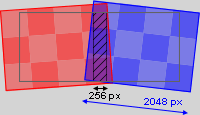 If you cannot see or measure the entire width, you can of course substitute the numbers, e.g. with half of the resolution and half of the width. Keep in mind, that the results gets less accurate the smaller your reference distance is. |
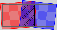
Now, let's look at the possibilities regarding the aspect ratio for projections without preplanned content that matches the screen. For this example, let's assume it is not possible to align the projectors better so the above image shows the starting point for the warping process.  However, with this result we obviously overshoot the screen. We cannot move the left and right side in, because this distorted the final aspect ratio. One solution would be to blank both areas. You can either apply a black image to a Layer and position it accordingly, or draw a mask that covers both sides, or apply a "Crop" effect to the Output Layer. Another solution is to use the possibility to change the aspect ratio of the Camera in the Camera Inspector. Simply measure the "on-screen" width depicted with the red and blue arrow and enter this with the on-screen height in the Inspector. This is also possible when the content was prepared with a certain aspect ratio. In that case you just need to make sure, that the projector covers the screen according to the plan and use this aspect ratio in the Inspector. If your test pattern or content was pre-defined and has a different resolution, e.g. 2000px, you can either scale the Layer with the factor 2048/2000=1.024 or reduce the Z-distance from the camera to the Layer. The default distance is -3000px, so the new distance would be -3000px / 1.024 = -2930px. Of course, you can also adjust the numbers by eye, without the need to calculate them exactly. If you would like to practice this to get a better understanding, you can do this also with a small projection, for example with one projector on a piece of paper. Draw an area on the paper and try to find the best and fastest way to project an image there using the above explained workflow with the Camera Inspector. Advanced users can also adopt the pixel conversion factor under Configuration tab > Unit Management. |
 |
 |
 |
 |
 |
Needless to say, it makes sense to use images as test pattern that cover the entire projection area and match the resolution of the content used in your show. In the best case, you have at least one background image that suits the needs of a test pattern. This means that it features circles and / or grid lines to make sure, the projectors overlap perfectly and form an image in the correct aspect ratio. Different colors and gradients help during the softedge process. If no images are available, you can also make use of the Stock Assets content found in the Assets tab. The sub folder "Testpattern" includes different test images in all kinds of resolutions. At best, you get familiar with an image editing software and workflows to create test pattern that suit your needs. Then you are flexible and prepared for the worst case as you can prepare or edit test images that fasten your warping work significantly and increase the quality of it.
It is also worth, to get familiar with the Mesh count setting. Each Mesh consists of horizontal and vertical lines anyhow so you can also orientate the warping by these lines. The following two paragraphs explain this in more detail.
This paragraph describes the difference between a Mesh point (Vertex) and an FFD point, thus it is covering a fundamental function of the warping process.
The pictures below show a 2D plane with a green-colored 10x10 Mesh and orange-colored 3x3 FFD.
See here the differences between moving a FFD control point and moving a Mesh point. Please note that the FFD is only a helping tool to set up the Mesh, you will not see the FFD in the final object.
|
|
|
Before you start moving the control points you have to decide with how many FFD control points and Mesh segments you want to work. The FFD and Mesh count is set up in the Sub Mesh Inspector. The perfect amount depends on your screen surface and outline.
The more warping projects you have done, the faster you will be able to tell the best FFD and Mesh count. If you are not sure in the beginning, simply make a guess and start warping. You will see quite fast, that you have picked too many or too less FFDs. Too many FFD points are not that bad, you simply spend more time in the FFD-phase but you could save time during the Mesh-phase - at least if not way too many FFDs were picked. If you have picked too less FFD points you will notice that you will have to move Mesh points at a very early stage of warping. This will definitely be more time-consuming than starting all over with a new Mesh. In addition, it is easier to obtain a good quality Mesh with FFDs instead of offsetting single Mesh points too far. If you would like to, you can save the current project and have a quick look whether a new Mesh with more FFDs does give you better results and eases your work. This can be found out in a few seconds but save minutes or even hours.
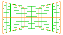 Example 1, a 4x3 FFD |
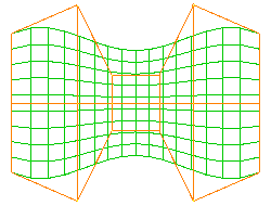 Example 2, a 6x3 FFD |
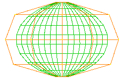 Example 3, a 5x5 FFD |
The amount of Mesh segments can be altered as long as working only with the FFD control points. As soon as a Mesh point is moved, the amount should not be changed any more as this will reset the Mesh and your changes will be lost.
In general, the amount of Mesh segments depends on how exact the warp needs to be. Firstly this is a question of how complex or detailed the screen is, including the outline, as shown in the above example with the simply bend screen. If the screen is quite flat itself but has a very detailed outline, it could be a faster solution to create a mask instead of increasing the Mesh count.
Secondly, it is important whether you are projecting with a single projector only, or if several projectors overlap each other. Within the softedge area the pixels from both projectors must overlay perfectly. This requires a higher Mesh count. As a rule of thumb, at least 7 Mesh segments should lie within the overlap area.
Many operators prefer to change the Mesh color for different outputs using the Inspector for the according Sub Mesh and its setting "Editing Wireframe Color". If you choose for example a red Mesh for one output and a green one for the other, it will become much easier to warp the overlap as both lines add up to a yellow color. However, please note that sometimes you can not bring the lines together. In those scenario your goal is to get the mesh lines parallel and with an equal distance. An example would be if you need to get the largest possible overlap and the amount of segments in the blend area cannot be a (reasonable) whole number. E.g., if the output resolution is 1280px and the overlap needs to be 400px and not any smaller!
By the way, it could be helpful to work with Mesh segments that have the same height as width because it is easier for the warping operator to see whether squares (in difference to rectangles) are equal. It also makes it easier to measure the screen and place markers. If your projector has an aspect ratio of 16:9, you could set up a Mesh count of 16 by 9 during the FFD-phase and increase it to 32 by 18 or even 48 by 27 before starting the Mesh-phase. As explained above under "Aspect Ratio", it is also possible to use the aspect ratio of the Camera or on-screen area, respectively.
With the rougher Mesh it is easier to see and get equal squares whilst moving the FFD points. Hence you have a very good basis when starting to work with the Mesh where the higher Mesh count might be needed because of details in the structure or an overlap with another projector. Doubling or tripling the Mesh count has the advantage that your markers on the screen still refer to existing Mesh lines. Alternatively you can also work with textures that show different grids as explained above under "Test Pattern".
The next chapter features a warping tutorial.