Loading...
The section "Preview Display" in the User category from the Configuration tab enables you to influence the appearance in the Preview tab. You can for example change the rendering of the Ground Grid, Gizmo and untextured objects. You can also open these settings through the right-click menu of the Preview tab > Preview Display Configuration.
Note that all settings here are for the local Preview only. To change the rendering appearance from all Client outputs, please go to the section "Client Display" or click the according button  .
.
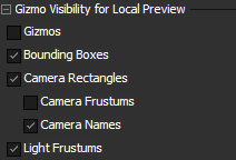
Gizmo Visibility for Local Preview "Gizmo" describes the icon with three axes in the colors red, green and blue. Many objects in Pandoras Box have a Gizmo: Layers, Cameras, Mesh points, etc. but they all work in the same way described in the chapter Gizmos and Wireframes in the Preview. Note that this check box is linked to the "Gizmo Visibility" button "Bounding Box" describes the blue box rendered around an object indicating its size. As long as you do not assign a three-dimensional object but work with flat 2D images or videos, the bounding box looks like a blue rectangle.
|
Likewise, a Light Device has its own icon and Frustum which can be toggled with the "Light Frustums" check box. Its style can be changed in the Light Inspector. |
Control Point Size in Local Preview |
Wireframe Visibility in Mesh Editing Mode The check box "For Editing Context" toggles the visibility of the Mesh grid (not the points itself!) for the Layer that is chosen in the "Editing Context" drop-down list, i.e. the Layer that is currently being warped and which is depicted with the editing icon in the Device Tree: The next check box "For all Editing Context Sibling Layers or Outputs" toggles the Mesh grid on all other Layers and Outputs. These means that you can toggle the Mesh from the Editing Context Layer and all other ones separately. This helps to align a Mesh to another one, e.g. within a softedge area where two Meshes overlap each other. The Mesh appearance, e.g. its color, can be changed in the Object Inspector. "Show FFD Edges" renders the lines between FFD points. |
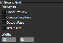
Ground Grid With these check boxes you may choose where the Ground Grid is displayed. The "Global Preview" refers to the view when the "Select Preview" drop-down list is set to "All cameras" as described in the chapter Select Preview: Camera or Output View. The Composition and Output Pass are described in the chapter Video Processing Pipeline. Venue Sites are explained in the chapter Venue Sites. - Width / Height |
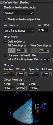
Mesh Shading and Color The left bottom example shows an untextured object with gray material color and blue wireframe edges. - Shade untextured object - Shade untextured particles - Wireframes - Width - Mesh Colors - Material - Global Point Light |